Method and apparatus for remotely monitoring a site

a remote monitoring and site technology, applied in the direction of testing/monitoring control systems, process and machine control, instruments, etc., can solve the problems of large quantities of data that cannot be easily transmitted to remote monitoring sites in real time, system has not achieved the wide spread use associated with binary off/on systems, and the number of video surveillance cameras is not only prohibitiv

Inactive Publication Date: 2005-07-12
NETTALON SECURITY SYST
View PDF16 Cites 145 Cited by
  • Summary
  • Abstract
  • Description
  • Claims
  • Application Information

AI Technical Summary

Benefits of technology

[0012]The network can be used to provide the primary visual alarm status reporting that gives the monitoring authority (user) the ability to identify the precise location of an intrusion / fire, and to distinguish false alarms. Multiple state, or multistate, indications are provided to represent a sensor. For example, each sensor can be identified as being: (1) currently in alarm; (2) currently in alarm and acknowledged by a monitor; (3) recently in alarm; (4) not in alarm; (5) disabled; or (6) a non-reporting alarm. With these multistate indications, the movements of an intruder or fire can be tracked, and yet the precise location of the intruder / fire can still be identified. This additional tracking ability gives police / firemen a tactical advantage at the scene as they know the location of the subject / fire and can track any subsequent movements as they close to make the arrest and / or fight the fire.

Problems solved by technology

However, because a large number of video surveillance cameras is not only cost prohibitive, but generates large quantities of data that cannot be easily transmitted to remote monitoring sites in real time, these systems have not achieved the wide spread use associated with binary off / on systems.
Thus, information such as the precise location of a potential intruder, is not provided for responding police officers.
More importantly, even when a large number of sensors is used to increase the resolution of alert information, the use of binary on / off indicators prohibits any ability to track an intruder's movement through the building and yet still be able to resolve the current location of the intruder.
In addition, known binary off / on systems cannot distinguish whether an alarm is real (i.e., genuine) or false.
When police arrive on the scene of a building where an alarm was tripped, they do not know whether the alarm is real or false and they are blind to what is inside the building.
Substantial time and money is expended in having police respond to large numbers of false alarms.
In situations where the alarms are valid, the police do not know this for certain, and can be taken by surprise.
The same drawbacks exists for fire monitoring and surveillance systems.
Although fire alarm systems are often tied directly into the local fire company, the false / real alarm discrimination, exact location of the fire, and the movement of the fire are unknown to the fire company which receives and responds to the alarm.

Method used


Image

  • Method and apparatus for remotely monitoring a site
  • Method and apparatus for remotely monitoring a site
  • Method and apparatus for remotely monitoring a site

Examples


Embodiment Construction

1. Functional Overview

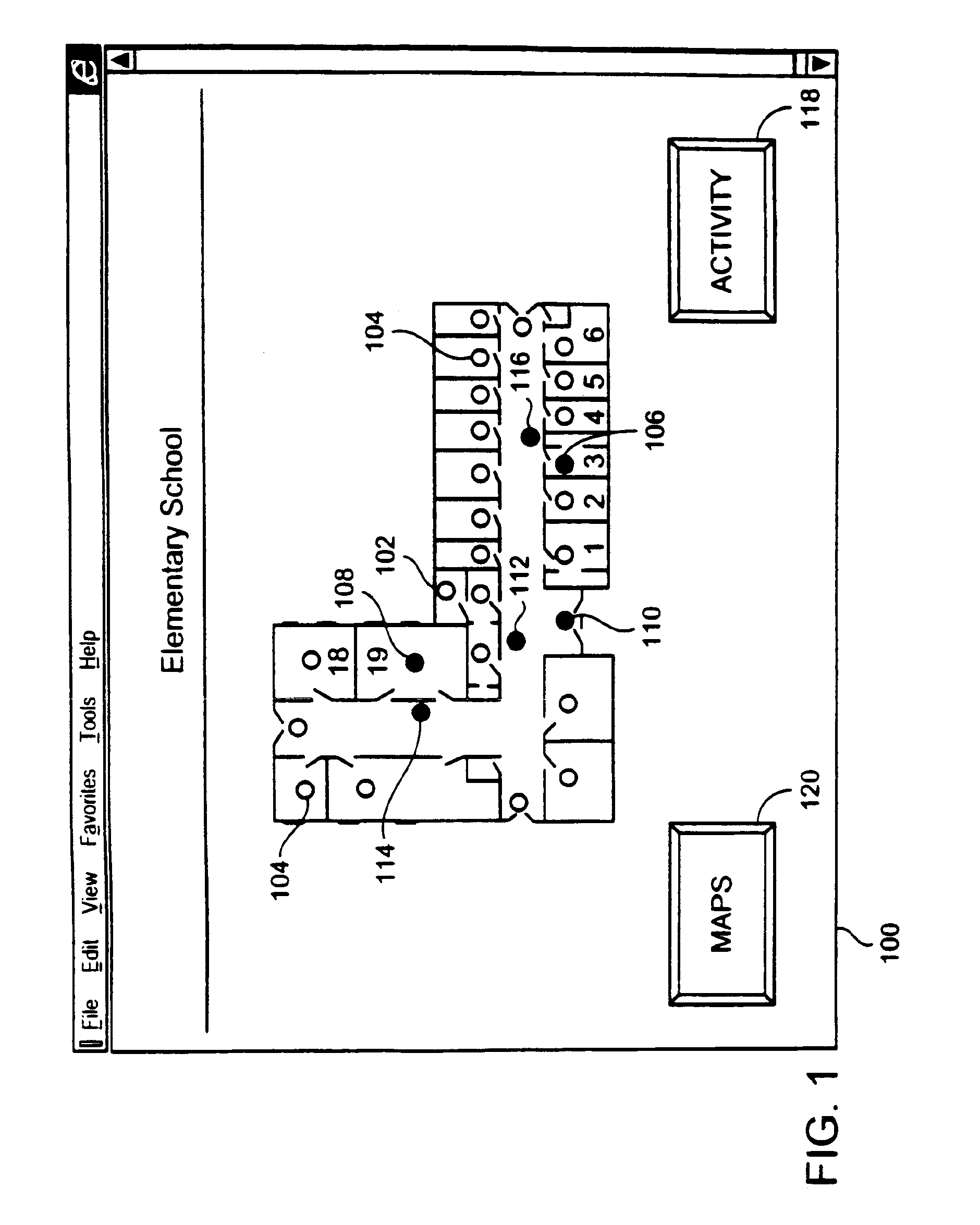
[0034]Before describing details of a system for implementing an exemplary embodiment of the invention, an overview of the invention will be provided using one exemplary display of information that is provided at a supervisory monitoring system's graphical user interface in accordance with the present invention. Referring to FIG. 1, the graphical user interface provides a screen display 100 of a particular floor plan 102 in a building being monitored for intrusion and / or fire detection. In the FIG. 1 example, a web browser included in the supervisory monitoring system is displaying a building floor plan 102 for an elementary school with its alarm points, and illustrates a two-person intrusion in progress. In this black / white rendition, points not in alarm are white circles 104. Two black circles 106, 108 indicate two points that are in simultaneous alarm. The gray filled circles 110, 112, 114 and 116 show alarms in a latched condition; that is, they were recentl...


PUM


Abstract

The present invention is directed to providing systems and methods for remotely monitoring sites to provide real time information which can readily permit distinguishing false alarms, and which can identify and track the precise location of an alarm. In embodiments, monitoring capabilities such as intrusion / fire detection and tracking capabilities, can be implemented through the use of multistate indicators in a novel interface which permits information to be transmitted using standard network protocols from a remote site to a monitoring station in real-time. In embodiments, communications can be handed from the centrally located host monitoring station to a mobile monitoring station (for example, a laptop computer in a responding vehicle, such as a police or fire vehicle). Additional embodiments include high, low, and rate-of-change alarms; chromagraphic representation of the value of an environmental or other parameter measured in a space; and detection and location of portable interface devices in a space.

Description

CROSS REFERENCE TO RELATED APPLICATIONS[0001]This application is a continuation-in-part of U.S. application Ser. No. 10 / 069,788, filed on Feb. 28, 2002 the United States national stage application under 35 U.S.C. § 371 of Patent Cooperation Treaty application Ser. No. PCT / US00 / 23974, filed Sep. 1, 2000, which is a continuation and claims priority to U.S. application Ser. No. 09 / 387,496, filed Sep. 1, 1999, and issued as U.S. Pat. No. 6,281,790.BACKGROUND OF THE INVENTION[0002]1. Field of the Invention[0003]The present invention relates generally to monitoring a remote site. More particularly, the present invention is directed to monitoring a remote site by providing real time transmission of outputs from a plurality of digital and / or analog multistate sensors which detect intrusion and / or fire or other environmental or other parameter, and communicate this information in an efficient, and effective format.[0004]2. Background Information[0005]Existing intrusion detection systems and ...

Claims


Application Information

Patent Timeline
IPC IPC(8): G08B25/14G08B13/194G08B13/196G08B19/00G08B25/08G08B25/10G08B29/00H04M11/00
CPCG08B13/19G08B13/19608G08B13/19645G08B13/19656G08B13/19682G08B13/19684G08B13/19691G08B13/19697G08B13/22G08B25/10G08B25/14G08B25/00
Inventor KIMMEL, DAVID E.BYRNE, JR., JAMES T.JONES, JR., DONALD R.DUBOIS, RONALD
Owner NETTALON SECURITY SYST
Why Eureka
Try Eureka