
Wireless communications cellular architecture for improving communications resource allocation

a wireless communication and cellular architecture technology, applied in the field of wireless systems, can solve the problems of limiting the overall capacity of the system, limiting the bandwidth of the system, and each cellular system having access to a very limited number of frequencies, so as to maintain acceptable quality of service requirements and reduce the frequency reuse factor

Inactive Publication Date: 2005-07-05
AT&T MOBILITY II LLC
View PDF13 Cites 2 Cited by
  • Summary
  • Abstract
  • Description
  • Claims
  • Application Information

AI Technical Summary

Benefits of technology

[0017]These needs and other needs are met by a method and apparatus for communications resource allocation in a wireless communications system having a total system bandwidth. A service area is divided into a plurality sectors. A first set of base station antennas are positioned within a first set of sectors. The first set of antennas have main beams set at a first set of angles, and each antenna corresponds to a sector within the first set of sectors. A s

Problems solved by technology

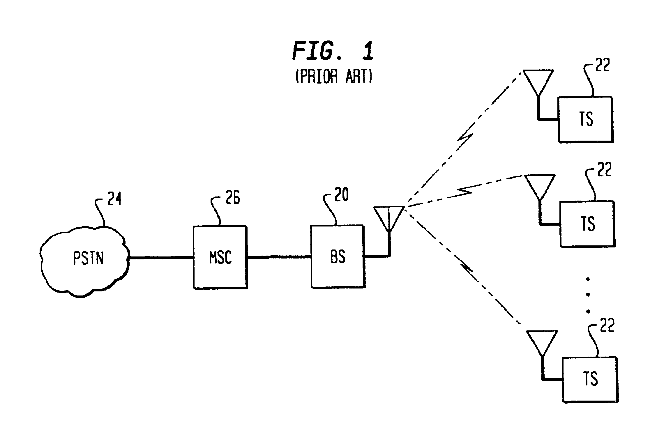
Bandwidth is a key limiting factor in determining the capacity of the system.
Consequently, each cellular system has access to a very limited number of frequencies.
This limits the overall capacity of the system, for example, by limiting the number of terminal stations that can communicate within a cell, or the data rates at which each terminal station can send and receive information.
Most of the undesired signal is due to co-channel interference.
Co-channel interference is interference due to the common use of the same frequency band by two different cells.
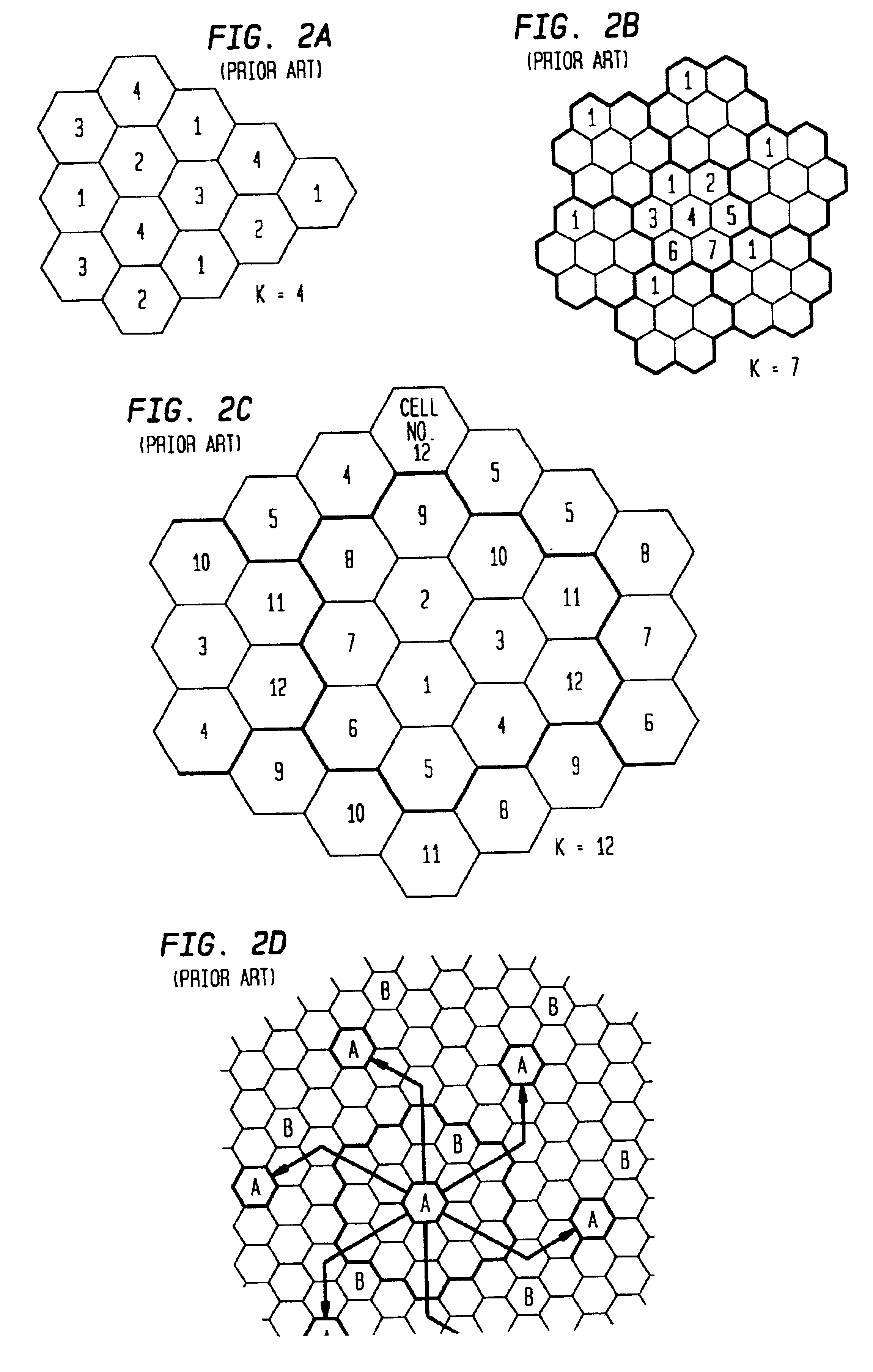
Thus, to a large extent, co-channel interference determines how often a set of frequencies may be reused throughout the entire system.
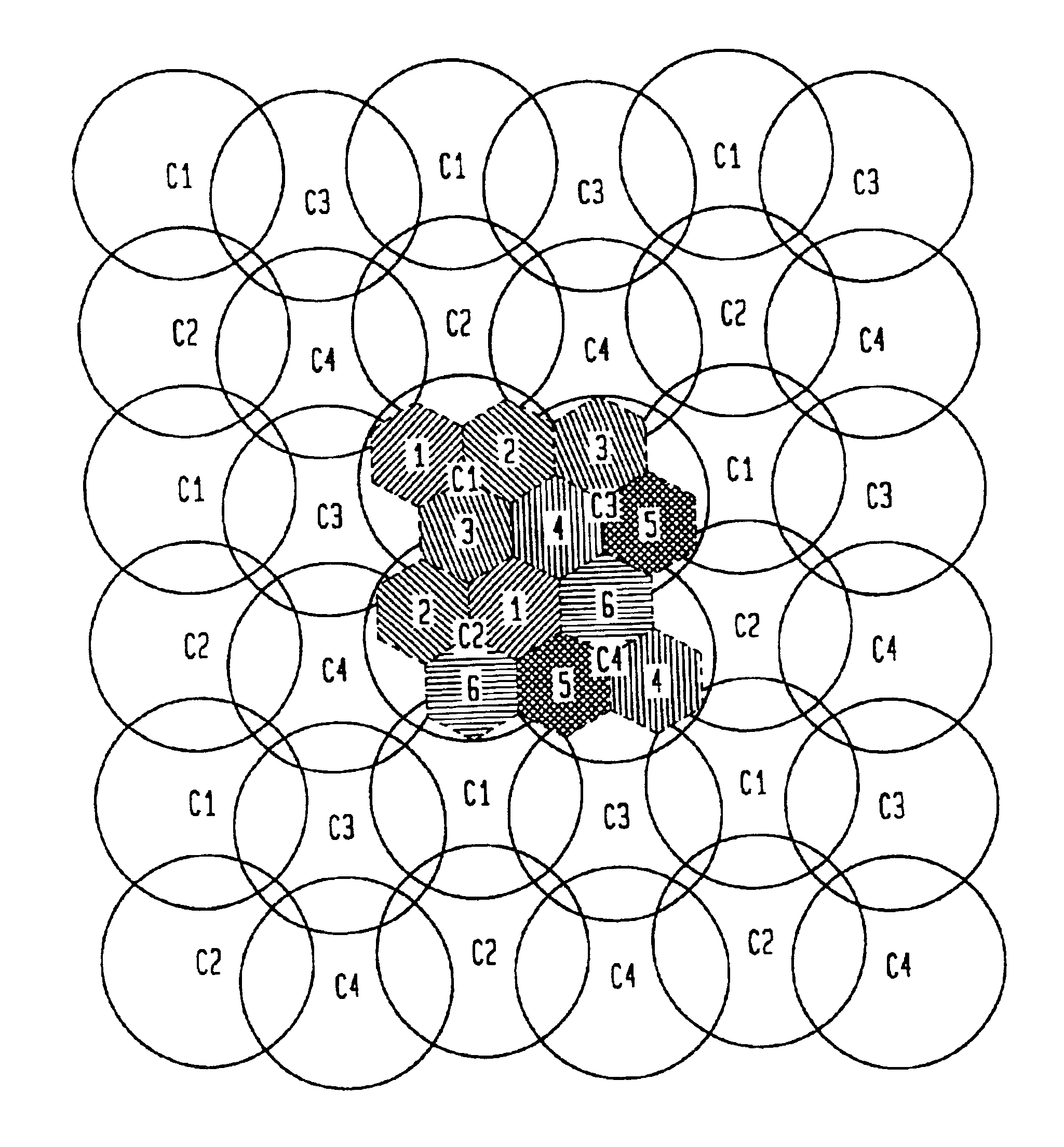
These cell configurations, however, are unsatisfactory for a number of reasons, which are described with reference to FIGS. 3, 4, and 5.

Method used


Image

  • Wireless communications cellular architecture for improving communications resource allocation
  • Wireless communications cellular architecture for improving communications resource allocation
  • Wireless communications cellular architecture for improving communications resource allocation

Examples


Embodiment Construction

[0030]The present invention comprises a cellular architecture and communications resource allocation method and apparatus that significantly reduces a frequency reuse factor for a wireless communications system. The capacity of a conventional cellular system is inversely proportional to the frequency reuse factor (i.e., K) for the system. A frequency reuse factor for conventional systems is typically K=7. The present invention reduces the frequency reuse factor to K=2, thereby tripling the capacity of many existing cellular systems, while maintaining acceptable quality of service (QoS) requirements.

[0031]A frequency reuse factor of K=2 is achieved using the following concepts. An advantageous embodiment of the invention uses a narrow beam trisector cell (NBTC) versus that of a wide beam trisector cell (WBTC) used in conventional systems. A NBTC uses an antenna for each sector having roughly half the beamwidth used in a WBTC. The base station antennas with smaller beamwidths used in ...


PUM


Abstract

A method and apparatus for communications resource allocation in a wireless communications system having a total system bandwidth. A service area is divided into a plurality sectors. A first set of base station antennas are positioned within a first set of sectors. The first set of antennas have main beams set at a first set of angles, and each antenna corresponds to a sector within the first set of sectors. A second set of base station antennas are positioned within a second set of sectors adjacent to the first set of sectors. The second set of antennas have main beams set at a second set of angles, and each antenna corresponds to a sector within the second set of sectors. Each sector is assigned a portion of the total system bandwidth.

Description

CROSS-REFERENCE TO RELATED PATENT APPLICATION[0001]This patent application is a continuation of 09 / 440,475 filed Nov. 15, 1999; which is a continuation of 08 / 862,095 filed May 22, 1997, now Pat. No. 6,002,935 issued Dec. 14, 1999.FIELD OF THE INVENTION[0002]The invention relates to wireless systems. More particularly, the invention relates to a method and apparatus for assigning communications resources for a wireless communications system.BACKGROUND OF THE INVENTION[0003]The demand for wireless communications services is on the rise. Cellular telephones are becoming as common as office and residential telephones. Personal Communications Service (PCS) offers the potential to improve existing cellular communications dramatically. Wireless high-speed broadband packet services hold promise for a whole host of new services for work-at-home, telecommuting, local and Internet access.[0004]As a result of the increased popularity of wireless communications services, bandwidth demands for wi...

Claims


Application Information

Patent Timeline
IPC IPC(8): H04Q7/36H04L12/56H04W16/02H04W16/12H04W16/24H04W16/30H04W72/04H04W84/04H04W88/08
CPCH04W16/02H04W16/12H04W72/0453H04W16/24H04W16/30H04W84/042H04W88/08
Inventor WANG, LI-CHUN
Owner AT&T MOBILITY II LLC
Learn More