
Wireless data transmission in CT-scanners

a technology of ct scanners and data transmission, applied in tomography, instruments, applications, etc., can solve the problems of inability to reliably transmit data in free space using electromagnetic waves, general noise in the immediate environment of the rotor, and inability to reliably detect contact slip rings, etc., to achieve the effect of simple gantry construction and easy detection

Inactive Publication Date: 2005-07-05
PHILIPS MEDICAL SYST TECH
View PDF17 Cites 24 Cited by
  • Summary
  • Abstract
  • Description
  • Claims
  • Application Information

AI Technical Summary

Benefits of technology

[0021]The inventors have realized that data can be reliably transmitted over free space at high data rates from detectors in a rotor of a CT-scanner to a desired location using spread spectrum coding of electromagnetic waves. Spread spectrum transmission is particularly robust and can be used to reliably and accurately transmit data between locations in an electronically noisy environment via free space electromagnetic waves.
[0022]In particular, a spread spectrum transmission technique referred to as “time hopping impulse modulation”, hereinafter “THIM”, can be used to support reliable, simultaneous data transmission from a large number of data sources located in a same localized noisy environment. In THIM transmission a signal is transmitted as a pulse train of very short pulses, referred to as impulses or monopulses. Each monopulse and a next subsequent monopulse in the pulse train are separated by a time period, referred to as pulse repetition intervals (PRI). The PRIs are generally much longer than a duration of a monopulse and may range from hundreds to thousands of times longer than a duration of a monopulse. The PRI between any two consecutive monopulses is regularly changed in accordance with a predetermined periodic “time hopping code”. Data is encoded into the pulse train by making changes in the PRIs, which are additional to those changes made responsive to the time hopping code, that are determined responsive to the data to be encoded. Many THIM transmitters operating in a same neighborhood can usually simultaneously transmit data to a same receiver without data transmitted by one of the transmitters interfering with data transmitted by another of the transmitters. Interference is generally prevented or substantially reduced by operating each of the different transmitters using a different time hopping code.
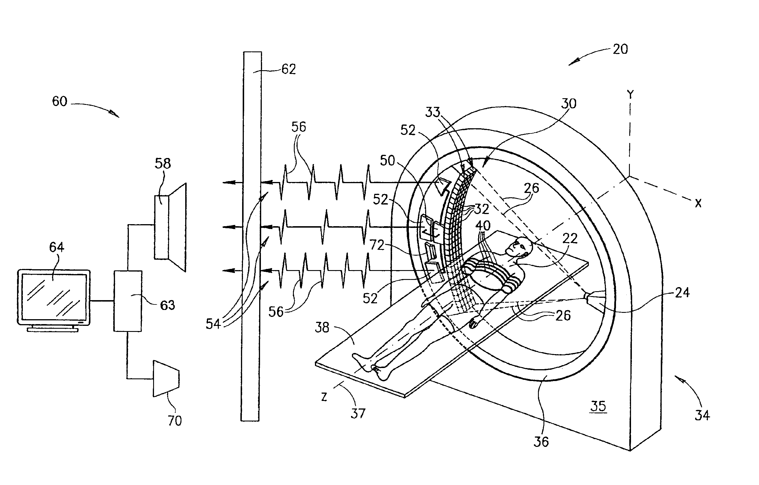
[0024]In accordance with an embodiment of the present invention, a CT-scanner is provided comprising a data transmission system having at least one THIM transmitter for transmitting data from X-ray detectors mounted on the rotor of the imager to a desired location. In some embodiments of the present invention, the at least one THIM transmitter transmits data from the detectors to a THIM receiver on the gantry stator. Unlike in prior art systems for transmitting data from the rotor to the stator, THIM transmission of data from the rotor to the stator, in accordance with an embodiment of the present invention, does not require that the THIM transmitter and receiver be in physical contact or in close proximity. As a result, use of THIM transmission simplifies construction of the gantry.

Problems solved by technology

However, the immediate environment of the rotor is generally electromagnetically very noisy.
As a result, free space transmission of the data using electromagnetic waves has not been considered practical.
Contact slip-rings generally cannot support reliable data transfer at data transfer rates that match rates at which modern third generation CT-scanner generate data.
However, currently available non-contact links for CT-scanners are generally expensive and they usually complicate mechanical construction of the imagers.
Furthermore, present non-contact links generally cannot support data transfer rates about equal to or greater than 1 Gbit / sec.

Method used


Image

  • Wireless data transmission in CT-scanners
  • Wireless data transmission in CT-scanners

Examples


Embodiment Construction

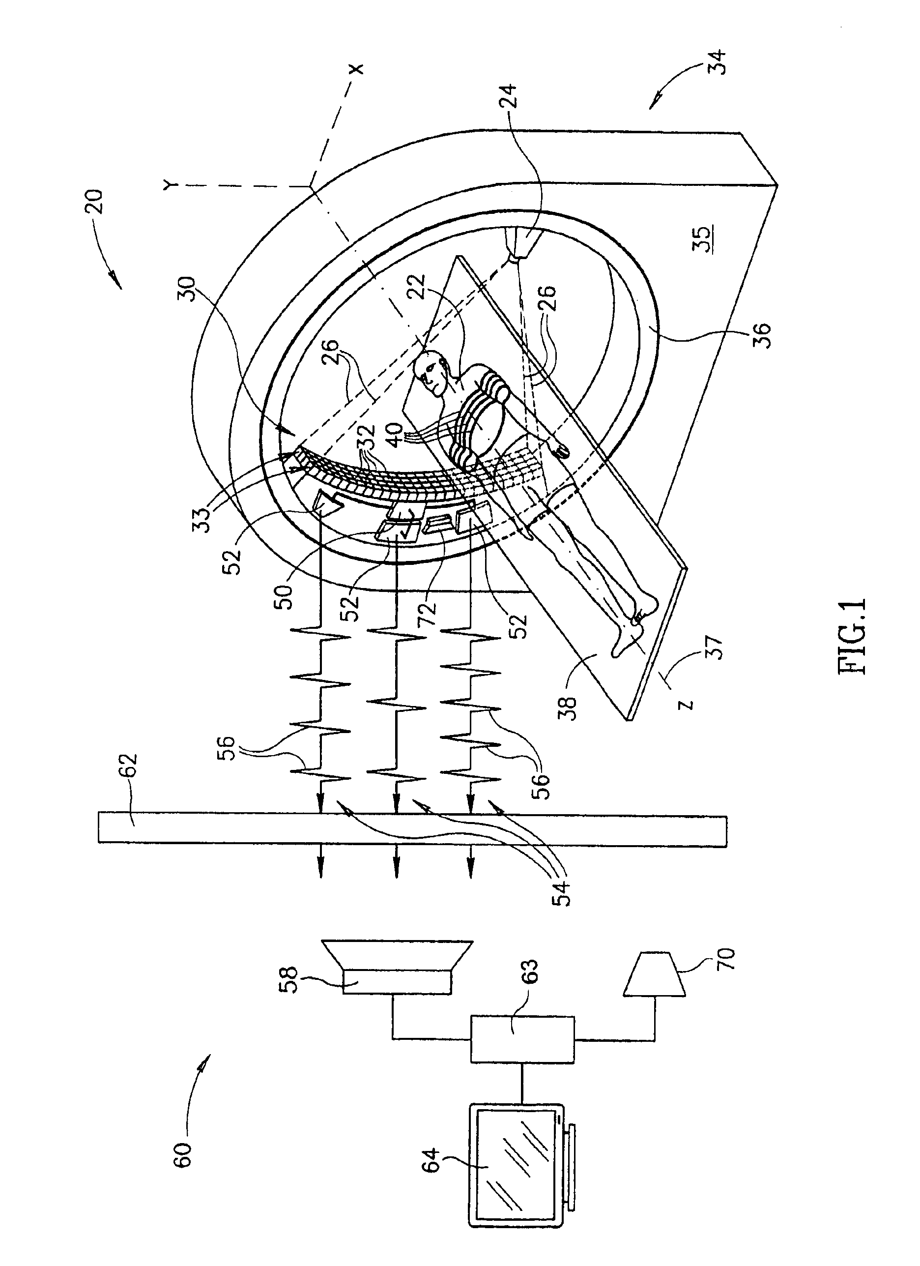
[0049]FIG. 1 schematically shows a third generation CT-scanner 20 comprising a THIM data transmission system, in accordance with an embodiment of the present invention. In FIG. 1, by way of example CT-scanner 20 is shown imaging a region of the chest of a patient 22. Dimensions of components and features shown in the FIGURE are chosen for convenience and clarity of presentation and are not necessarily shown to scale.

[0050]CT-scanner 20 comprises an X-ray source 24 controllable to provide a fan-beam schematically indicated by dashed lines 26 and an array 30 of X-ray detectors 32 mounted opposite the X-ray source for sensing X-rays in the fan-beam. CT-scanner 20 is assumed, by way of example to be a multislice imager that simultaneously images a plurality of four slices of a region of the body of a patient (patient 22 in FIG. 1) being imaged with the CT-scanner. Detectors 32 in array 30 are therefore configured in a plurality of four contiguous curved rows 33 of the detectors. CT-scan...


PUM


Abstract

A CT-scanner having a gantry comprising a stator and a rotor, wherein an X-ray source and array of X-ray detectors are mounted to the rotor for determining absorption of X-rays along paths through the body of a patient imaged by the CT-scanner, the CT imager comprising: a processor that processes data comprised in signals generated by the X-ray detectors responsive to intensity of X-rays from the X-ray source incident on the detectors to generate an image of the patient; at least one spread spectrum transmitter that receives data comprised in the signals generated by the X-ray detectors and transmits signals encoded with the data in accordance with a spread spectrum coding; and at least one spread spectrum receiver that receives the encoded signals transmitted by the at least one spread spectrum transmitter and forwards the encoded data to the processor.

Description

RELATED APPLICATIONS[0001]This application is a U.S. national filing of PCT Application No. PCT / US01 / 49152, filed on Dec. 19, 2001.FIELD OF THE INVENTION[0002]The present invention relates to computerized tomography (CT) X-ray imaging, and in particular to methods to methods and apparatus for transmitting data generated by X-ray detectors in a CT-scanner to a processor that generates and displays images responsive to the data.BACKGROUND OF THE INVENTION[0003]In CT X-ray imaging of a patient, X-rays are used to image internal structure and features of a region of the person's body. The imaging is performed by a CT-imaging system, hereinafter referred to as a “CT-scanner” that images internal structure and features of a plurality of contiguous relatively thin planar slices of the body region using X-rays.[0004]The CT-scanner generally comprises an X-ray source that provides a planar, fan-shaped X-ray beam and an array of closely spaced X-ray detectors that are coplanar with the fan be...

Claims


Application Information

Patent Timeline
IPC IPC(8): A61B6/03A61B6/00
CPCA61B6/032A61B6/56
Inventor DAFNI, EHUDGREEN, JAMES W.
Owner PHILIPS MEDICAL SYST TECH
Learn More