
Shading correction method for heat development recording apparatus and heat development recording apparatus

Inactive Publication Date: 2005-07-05
FUJIFILM HLDG CORP +1
View PDF9 Cites 2 Cited by
  • Summary
  • Abstract
  • Description
  • Claims
  • Application Information

AI Technical Summary

Benefits of technology

[0014]It is an object of the present invention to solve the problems of the related art and provide a shading correction method for a heat development recording apparatus and a heat development recording apparatus in which while a good shading correction function is maintained, the increase of cost due to mounting of a highly accurate and expensive density measuring unit can be suppressed.
[0020]In this heat development recording apparatus, before the recording apparatus is shipped, the first shading correction pattern continuously recorded on the recording surface can undergo a highly accurate shading correction by employing the first accurate recording density measuring unit for measuring the recording density for each pixel. Further, after the recording apparatus is shipped, the second shading correction pattern discretely recorded on the recording surface can undergo a simple shading correction by employing the second recording density measuring unit for measuring the recording density for each discrete recording position. Accordingly, an expensive recording density measuring unit does not need to be mounted on the heat development recording apparatus and a cost can be decreased. Further, the shading correction after shipment of the heat development recording apparatus may be carried out only by measuring the density for each discretely recorded position. Consequently, the recording density can be simply measured.

Problems solved by technology

Then, a highly accurate and expensive recording density measuring unit used when the shading correction is carried out is removed and the heat development recording apparatus is shipped without mounting the recording density measuring unit thereon.

Method used


Image

  • Shading correction method for heat development recording apparatus and heat development recording apparatus
  • Shading correction method for heat development recording apparatus and heat development recording apparatus
  • Shading correction method for heat development recording apparatus and heat development recording apparatus

Examples


Embodiment Construction

[0029]Now, referring to the drawings, preferred embodiments of a shading correction method for a heat development recording apparatus and a heat development recording apparatus according to the present invention will be described in detail.

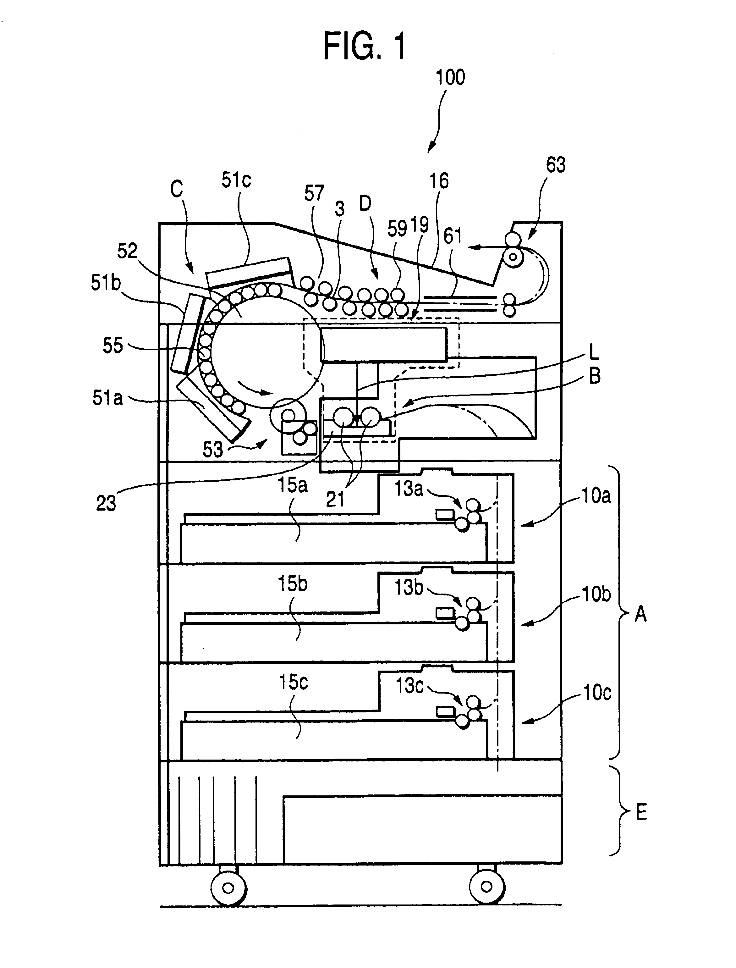
[0030]FIG. 1 shows a schematic side view of a heat development recording apparatus according to the present invention. A heat development recording apparatus 100 is generally an apparatus that uses a heat development recording material requiring no wet type developing process, exposes the heat development recording material by scanning and exposure by light beam L composed of laser beam to form a latent image, then, obtains a visible image by carrying out a heat development, and cools the heat development recording material having the visible image to ordinary temperature and outputs the heat development recording material.

[0031]The heat development recording apparatus 100 is basically provided with a heat development recording material supply par...


PUM


Abstract

Upon adjustment before the adjustment of a heat development recording apparatus, a continuous recording pattern is outputted. The recording density of this continuous recording pattern is measured by a recording density measuring unit. A shading correction table for each pixel is formed and the shading correction table is registered in a storing unit. On the other hand, after the heat development recording apparatus is shipped without mounting the recording density measuring unit thereon, a discrete recording pattern is outputted. The recording density of the discrete recording pattern is measured for each discrete recording position to generate a shading correction table. The shading correction table registered in the storing unit is updated. Therefore, it is possible to reduce a cost while a good shading correction function is ensured.

Description

BACKGROUND OF THE INVENTION[0001]1. Field of the Invention[0002]The present invention relates to a shading correction method for a heat development recording apparatus in which a heat development recording material is exposed to a laser beam, and then, the heat development recording material is thermally developed and a heat development recording apparatus.[0003]2. Description of the Related Art[0004]In recent years, the amount of processed waste liquid has been eagerly requested to decrease from the viewpoints of environmental protection and space saving in a medical field. Thus, a technique concerning photosensitive and heat development photographic materials utilized for a medical diagnosis and a usage of photographic technique which can be efficiently exposed by a laser image setter or a laser imager and can form a clear black image having a high resolution and a sharpness has been required. These photosensitive heat development recording materials allow the use of solution type...

Claims


Application Information

Patent Timeline
IPC IPC(8): H04N1/401B41J2/52
CPCH04N1/4015
Inventor KOJIMA, TETSUYA
Owner FUJIFILM HLDG CORP
Learn More