
Method and system for high resolution display connect through extended bridge

a high-resolution display and extended bridge technology, applied in the field of high-resolution display systems, can solve the problems of too fast for the graphics adaptor, waste of resources, and inability to handle efficiently, so as to achieve efficient and easy connection to the display, avoid bottlenecks, and achieve high resolution.

Inactive Publication Date: 2005-07-05
IBM CORP
View PDF4 Cites 3 Cited by
  • Summary
  • Abstract
  • Description
  • Claims
  • Application Information

AI Technical Summary

Benefits of technology

[0017]In a third aspect, a method of decreasing a bottleneck in a communications bus, includes providing an extended bus bridge between a graphics adaptor and a central processing unit (CPU),and localizing the graphics adaptor to a display monitor.
[0019]Moreover, the invention takes the graphics adaptor away from the system PC box and instead places the graphics adaptor with the monitor. Thus, the graphics adaptor is “localized” with the monitor (e.g., placed / positioned with or in the monitor), thereby avoiding the bottleneck caused by the cable having to carry all of the bandwidth of the high resolution image.
[0021]Thus, with the unique and unobvious features of the invention, as flat panel display technology pushes towards higher resolutions and surpasses the capabilities of current CRT monitors, the computer can be efficiently and easily connected to the display without any bottleneck being created.
[0022]That is, even when the bandwidth requirements increase drastically when increasing the resolution or refresh rate of a monitor (e.g., even a digitally-driven flat panel monitor), there is no bottleneck between the connection between the PC and the monitor.
[0023]Additionally, because the adapter is in the display, the connection between the adapter and the display can be parallel, not serial (e.g., as shown in FIG. 3 and described below). This means that the frequency of operation can be reduced and still maintain a high bandwdith. Also, because the high bandwdith connections are local to the display, the EMI can be minimized. Moreover, the EMI characteristics of the cable (e.g., always a large source of radiation) now do not change with frame rate or display type. The characteristics are dependent upon the rate of the bus, which is typically “bursty” but fixed, and thus it is much easier and cheaper to characterize and shield. Because the high bandwidth lines are in the display, their length is made much shorter as well, thereby helping to reduce power. Further, because the connection mechanism is not dedicated to the display and is by its nature “two-way”, additional input and output devices can be added to the display by adding additional connection support.

Problems solved by technology

As flat panel display technology pushes towards higher resolutions and actually surpasses the capabilities of current CRT monitors, the question of how to connect the computer to the display becomes an issue.
That is, a problem with the architecture shown in FIG. 1 is that the cable 102 from the graphics adaptor 104 in the PC box 110 to the monitor 101 carries faster information (i.e., pixel by pixel description of the image at 60+Hz refresh rate) which is too fast for the graphics adaptor 104 / monitor 101 to handle efficiently.
As mentioned above, with digital signals becoming more prevalent, more data (e.g., in the form of higher refresh rates, higher pixel counts, a higher number of colors, etc.) will be provided to the graphics adaptor, thereby leading to higher bandwidth requirements and hence the bottleneck.
Currently, the monitor is “dumb” and only knows what pixels to place at which point Thus, the higher resolution displays will cause a severe bottleneck between the graphics adaptor and the monitor.
Additionally, there are electromagnetic induction (EMI) and power dissipation problems.
That is, because this system configuration forces a serial connection, the frequency of transmission is high and this aggravates power and EMI.
These additional connections are not possible with the current dedicated display connections.

Method used


Image

  • Method and system for high resolution display connect through extended bridge
  • Method and system for high resolution display connect through extended bridge
  • Method and system for high resolution display connect through extended bridge

Examples


first preferred embodiment

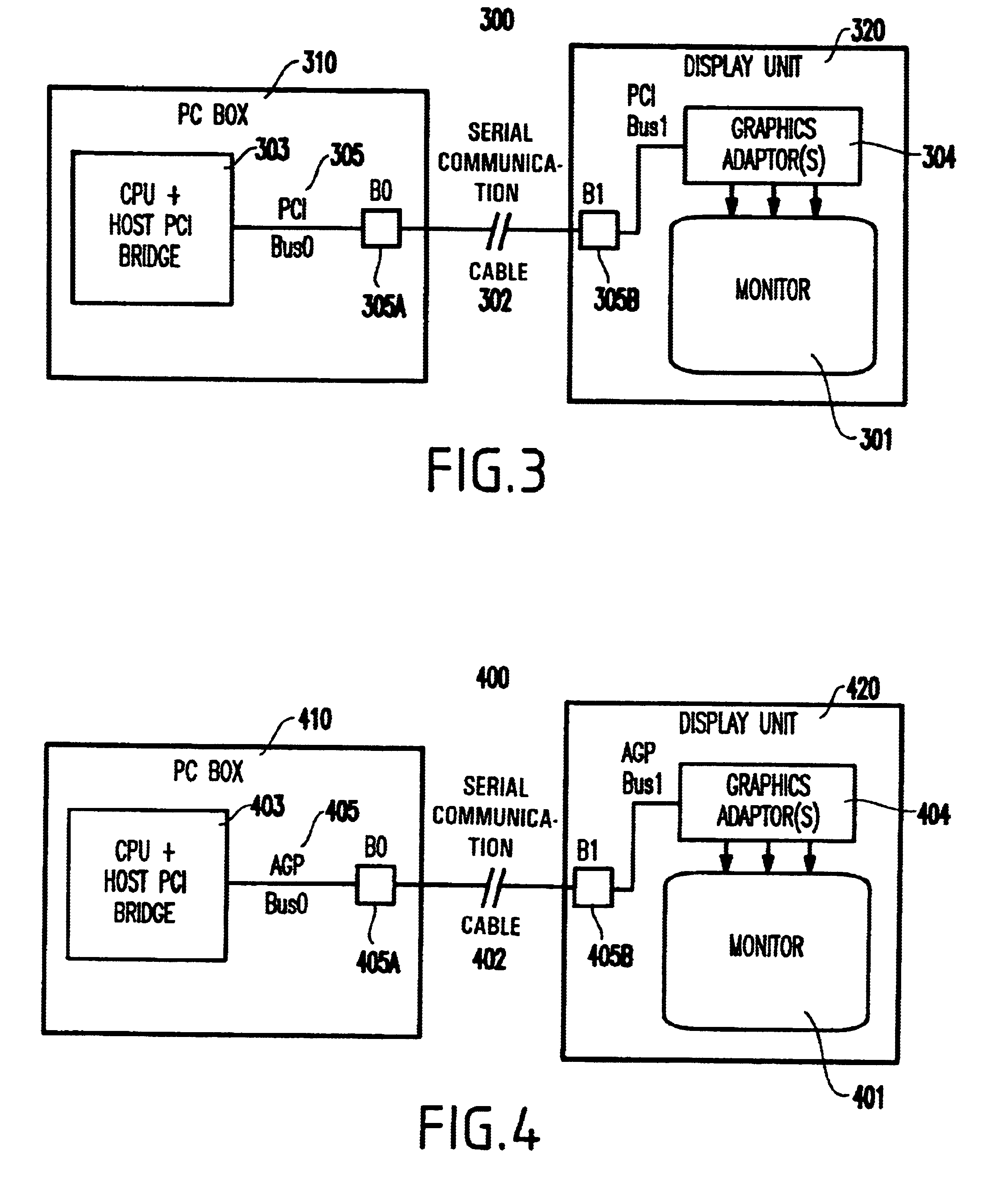
[0030]To attack the above problems of the conventional architectures, the inventive solution extends the PCI bus by using an extended PCI-PCI bridge and colocates the graphics adaptor(s) with the display itself rather than inside the PC Box 310.

[0031]That is, as shown in FIG. 3, a system 300 according to the invention includes a PC Box 310 coupled to a display unit 320 via a cable 302. As shown in FIG. 3, the invention has moved the graphics adaptor 304 as shown to be a part of the display unit 320 and localized to the monitor 301.

[0032]The invention utilizes an extended bus bridge 305. In FIG. 3, the bus bridge is shown preferably as a PCI bus bridge 305 having a bus portion 305A on the CPU side and a bus portion 305B on the monitor side. The invention is not limited to the PCI bus bridge and indeed other bus bridges may be employed. For example, as discussed in further detail below, in the second embodiment of the invention, an Accelerated Graphics Port (AGP) bus bridge (e.g., hav...

second preferred embodiment

[0041]As mentioned above, the invention is not limited to the PCI bus bridge and indeed other bus bridges may be employed.

[0042]For example, as shown in FIG. 4, in the second embodiment of the invention, an Accelerated Graphics Port (AGP) bus bridge may be provided instead of the PCI bus bridge. Instead of B0 in FIG. 3, in FIG. 4 a first portion of the AGP bus bridge can be provided on the PC side. Similarly, a second portion of the AGP bus bridge can be provided on the display unit side.

[0043]Thus, with the unique and unobvious aspects of the present invention, the invention provides an extended PCI-PCI Bridge or an extended AGP bridge for connecting the computer to the display subsystem.

[0044]Moreover, the invention takes the graphics adaptor away from the system PC box and instead places the graphics adaptor with the monitor. Thus, the graphics adaptor is localized with the monitor, thereby avoiding the bottleneck caused by the cable having to carry all of the bandwidth of the hi...


PUM


Abstract

A method of (and system for) of displaying information, includes an extended bus bridge, a graphics adaptor coupled to the extended bridge, and a monitor coupled to the graphics adaptor to display the information, such that the graphics adaptor is localized to the monitor.

Description

BACKGROUND OF THE INVENTION[0001]1. Field of the Invention[0002]The present invention relates to a method and display system for displaying an image with high resolution, and more particularly to a method and display system for displaying an image through an extended Peripheral Component Interconnect (PCI) to PCI bridge.[0003]2. Description of the Related Art[0004]FIG. 1 illustrates a generic architecture for a conventional system 100 including a monitor display 101 connected, via a cable 102, to a personal computer (PC) box 110 including a central processing unit (CPU) and host Peripheral Component Interconnect (PCI) bridge 103 and graphics adaptor 104.[0005]In such systems, there is an increasing trend to replace analog cathode ray tube (CRT) desktop monitors 101 with flat panel display monitors. Various factors contribute to this trend including desktop space saving, power saving, higher resolution and crisper images.[0006]As flat panel display technology pushes towards higher re...

Claims


Application Information

Patent Timeline
IPC IPC(8): G06F13/00G06F13/14G06F3/14G09G5/36
CPCG06F3/14G09G5/36G09G2330/06G09G2340/0407
Inventor ASAAD, SAMEH W.WARREN, KEVIN W.
Owner IBM CORP
Learn More