
Keypad device

a keypad and keypad technology, applied in the field of keypad devices, can solve the problems of reducing the overall design footprint of a product or product component, severely restricting the space available for other components directly under the keypad, and affecting the use of mobile telephone keypads, etc., and achieves the effect of reducing the overall design footprint and being easily extended to electronic devices

Inactive Publication Date: 2005-06-28
SNAPTRACK
View PDF10 Cites 34 Cited by
  • Summary
  • Abstract
  • Description
  • Claims
  • Application Information

AI Technical Summary

Benefits of technology

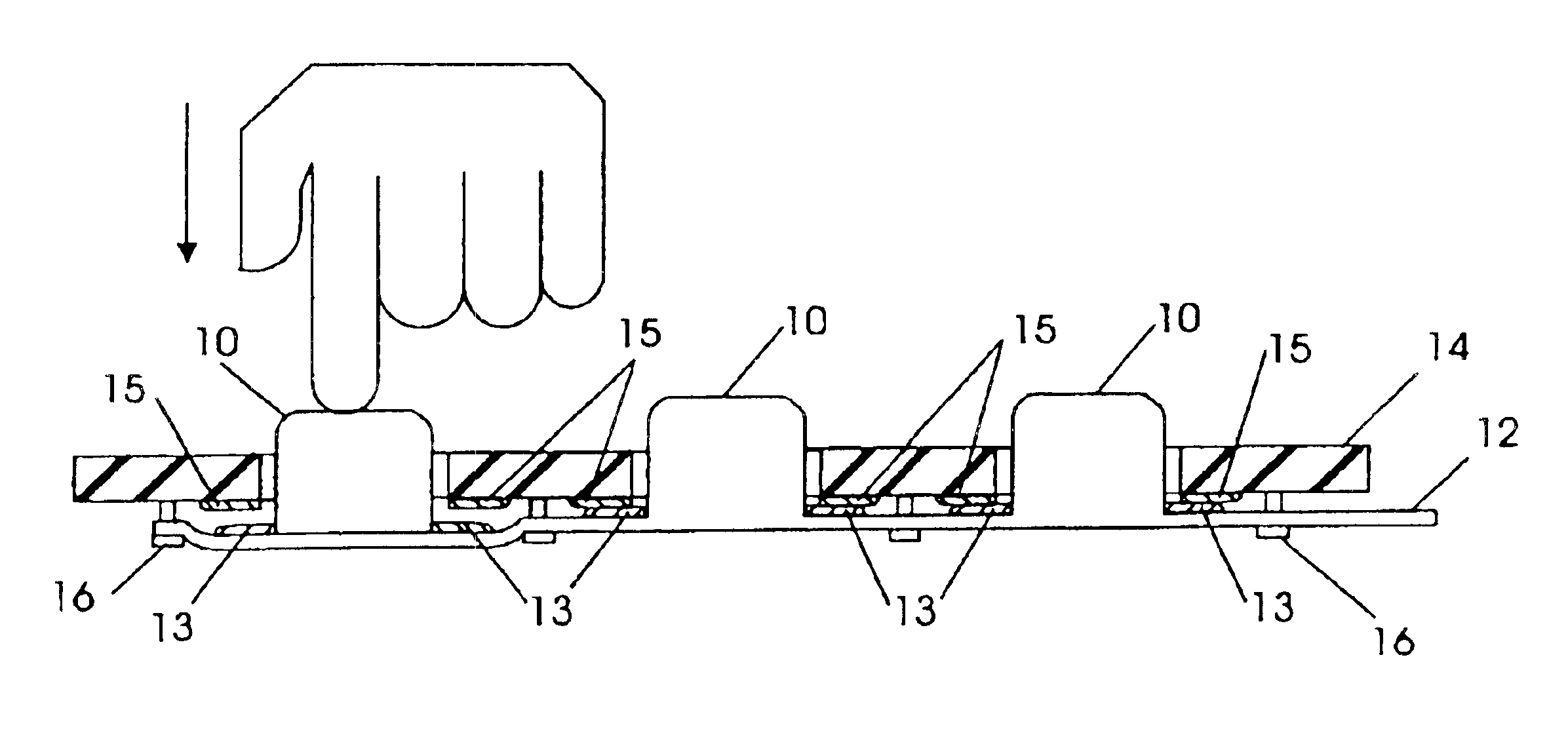
[0007]The present invention comprises a keypad design for a mobile telephone that allows the area directly beneath the keypad on the main printed circuit board (PCB) of the mobile telephone to be used for circuitry other than keypad contacts. Or, if other circuitry is not desired, the overall mobile telephone design may be compressed into a thinner profile. The present keypad design is readily extendable to electronic devices other than mobile telephones.

Problems solved by technology

Using less space for component(s) leads to a smaller footprint for the overall design of a product or product component.
This severely limits the printed circuit board (PCB) space available for other components directly under the keypad.
The same limitations described for mobile telephone keypads also apply to other electronics devices that require a keypad or keyboard of some sort.

Method used


Image

  • Keypad device
  • Keypad device
  • Keypad device

Examples


Embodiment Construction

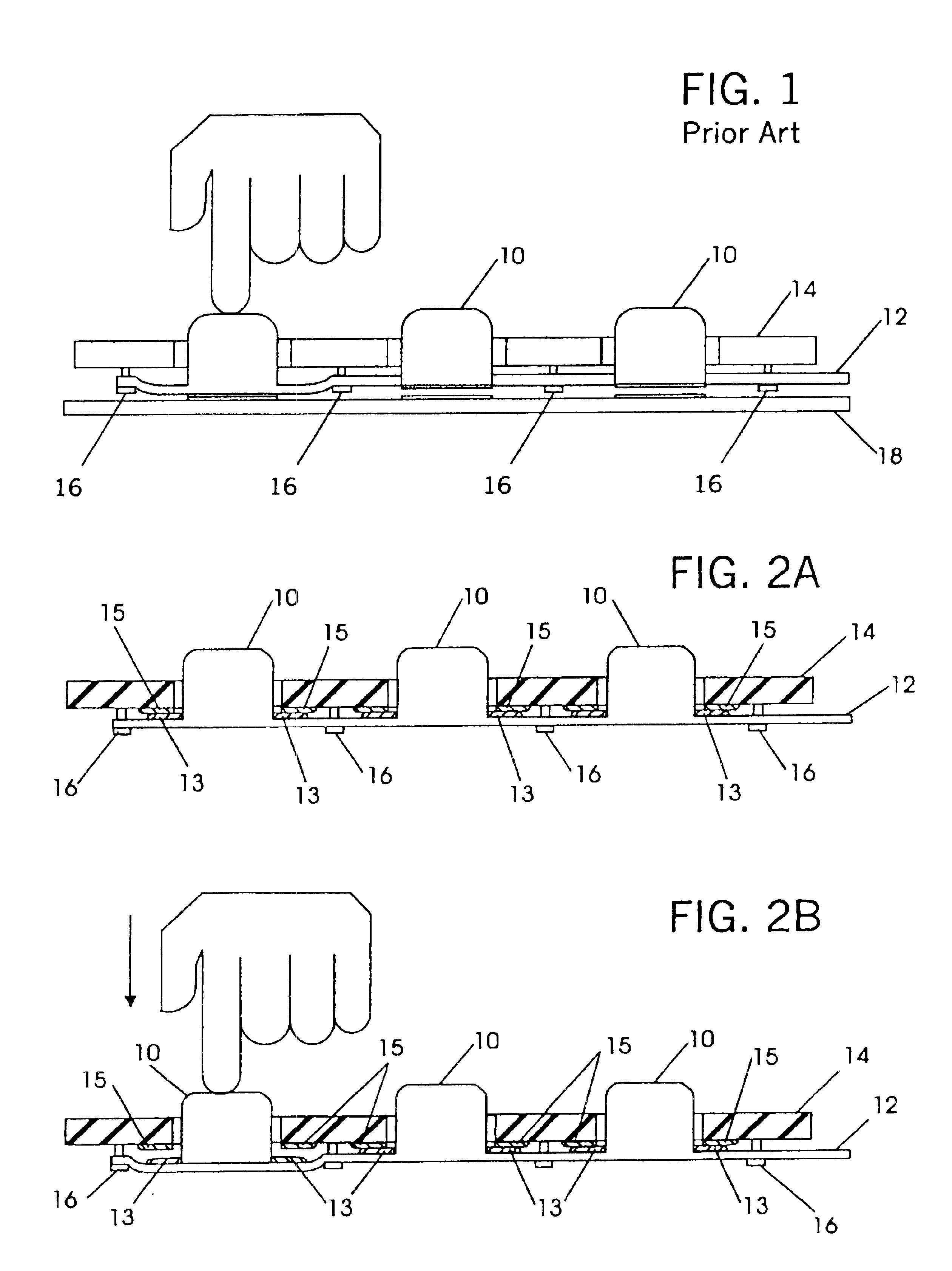
[0019]FIG. 1 illustrates a typical prior art mobile telephone keypad design. The keypad design comprises a keypad including a plurality of keys 10 that are mounted to a flexible substrate 12. The flexible substrate 12 is coupled with the cover of the mobile telephone 14 which holds the keys in place and exposes the keys for depression from an external force such as a finger depression. The interior surface of the cover of the mobile telephone 14 and the flexible substrate 12 are spaced apart slightly and coupled via a plurality of stand-offs 16. A standoff is typically a plastic pin or other material that secures the flexible substrate 12 to the mobile telephone cover 14 at a fixed distance. The entire keypad device is positioned above a printed circuit board (PCB) 18. The underside surface of each key 10 is comprised of, or coated with, a conductive material such that when a key 10 is depressed it comes into contact with the printed circuit board (PCB) 18 completing a circuit and i...


PUM


Abstract

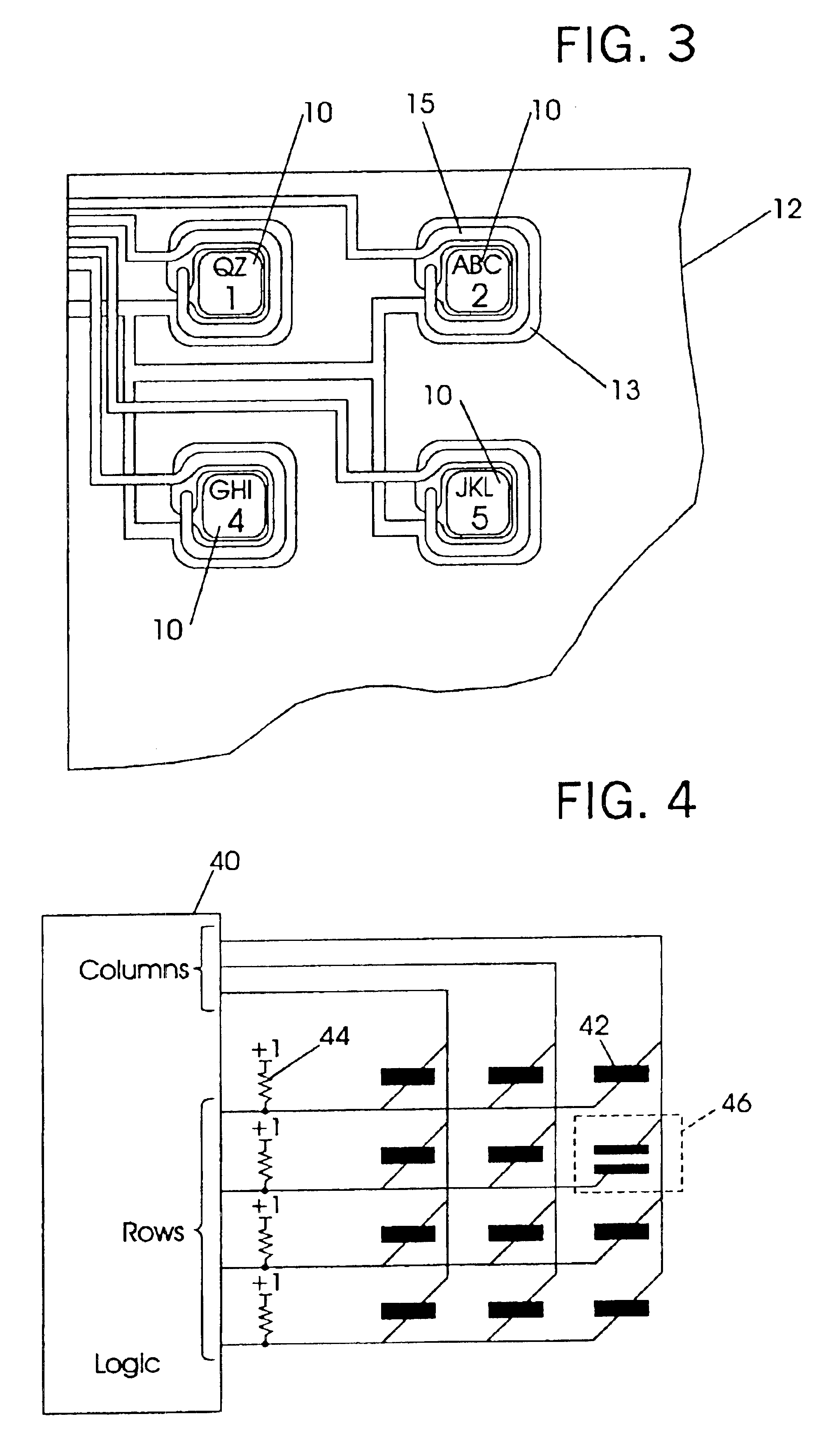
A keypad device for a mobile telephone or other device utilizing a keypad or keyboard is comprised of a flexible substrate and a keypad cover. The flexible substrate includes a plurality of keys affixed to the surface as well as a plurality first conductive strips associated with each key. The keypad cover is attached to the flexible substrate. The keypad cover typically includes holes that permit the plurality of keys to protrude through the keypad cover. In addition, the keypad cover further includes a plurality of second conductive strips that selectively contact a corresponding first conductive strip on the flexible substrate. The plurality of first conductive strips is coupled to ground and the plurality of second conductive strips is coupled to logic circuitry. Or, in another embodiment, both sets of conductive strips are coupled with the logic circuitry. The default position of the keypad device has each of the first conductive strips in contact with each of the corresponding second conductive strips. This creates a short circuit condition that prevents key signals from being received by the logic circuitry. When a particular key is depressed to the point where the first conductive strip associated with that particular key is separated from the second conductive strip corresponding to the first conductive strip, the short circuit condition is removed. This allows a signal to be transmitted to and processed by the logic circuitry indicating that a particular key has been selected.

Description

BACKGROUND OF THE INVENTION[0001]One concern in electronics design is space savings. Using less space for component(s) leads to a smaller footprint for the overall design of a product or product component. This permits an electronics product to be made smaller or more components may be added to the original footprint.[0002]This is especially relevant to circuit board components where space is at a premium. Any conservation measures that can be applied to printed circuit boards (PCBs) are considered extremely valuable because of the resulting decreased footprint or increased density of circuit board components. Increased density yields more electronics components per unit area and that translates into increased functionality for the electronics product.[0003]One particular electronics product that strives to decrease its physical size and increase its functional capabilities is the mobile telephone. Today's mobile telephones are sleek, ultra-thin, and ultra-lite designs when compared...

Claims


Application Information

Patent Timeline
IPC IPC(8): H01H13/70H01H13/702
CPCH01H13/702H01H2003/146E05F2015/447H01H2205/002H01H2225/012H01H2203/03
Inventor HENRY, RAYMOND C.
Owner SNAPTRACK
Learn More