
Shielded cable end connector assembly

a technology of shielding protection and connector assembly, which is applied in the direction of coupling device connection, coupling device details, and coupling protective earth/shielding arrangement, etc., can solve the problem that the current structure of the serial ata cable connector assembly does not have shielding protection to the housing portion, and achieve better shielding protection

Inactive Publication Date: 2005-06-28
HON HAI PRECISION IND CO LTD
View PDF13 Cites 55 Cited by
  • Summary
  • Abstract
  • Description
  • Claims
  • Application Information

AI Technical Summary

Benefits of technology

[0006]An object of the present invention is to provide a cable end connector assembly having quick-assembled shielding member for providing better shielding protection to the signal transmission.

Problems solved by technology

However, current structure of a Serial ATA cable connector assembly has no shielding protection to the housing portion.

Method used


Image

  • Shielded cable end connector assembly
  • Shielded cable end connector assembly
  • Shielded cable end connector assembly

Examples


Embodiment Construction

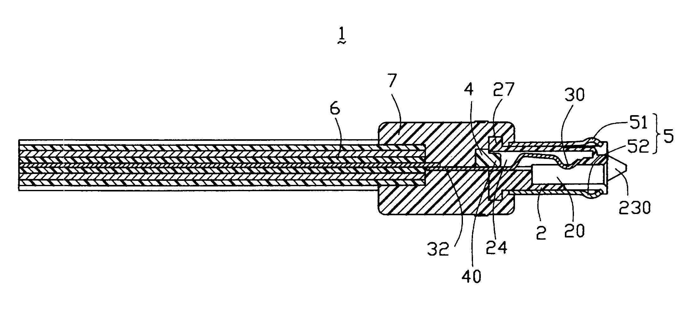
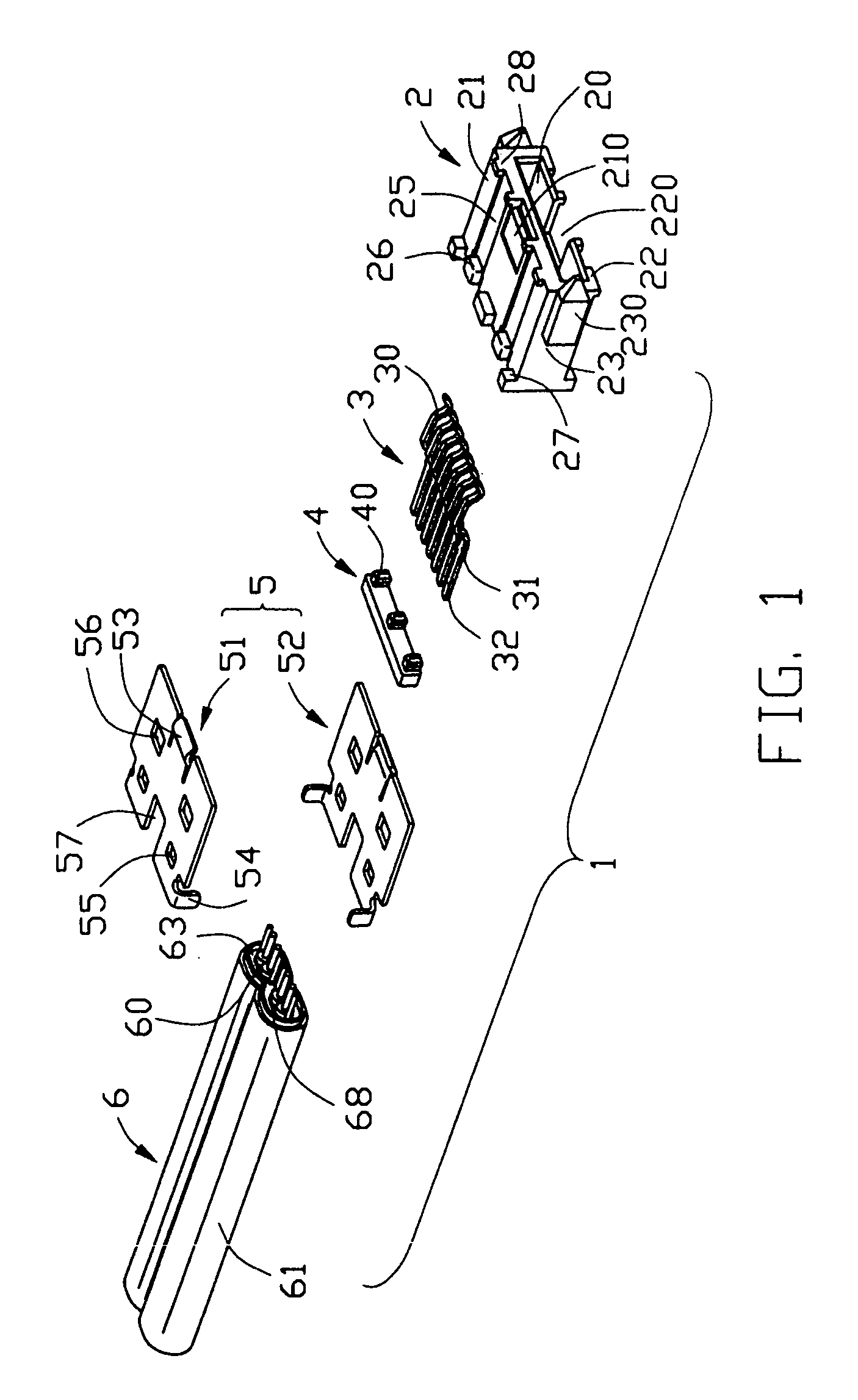
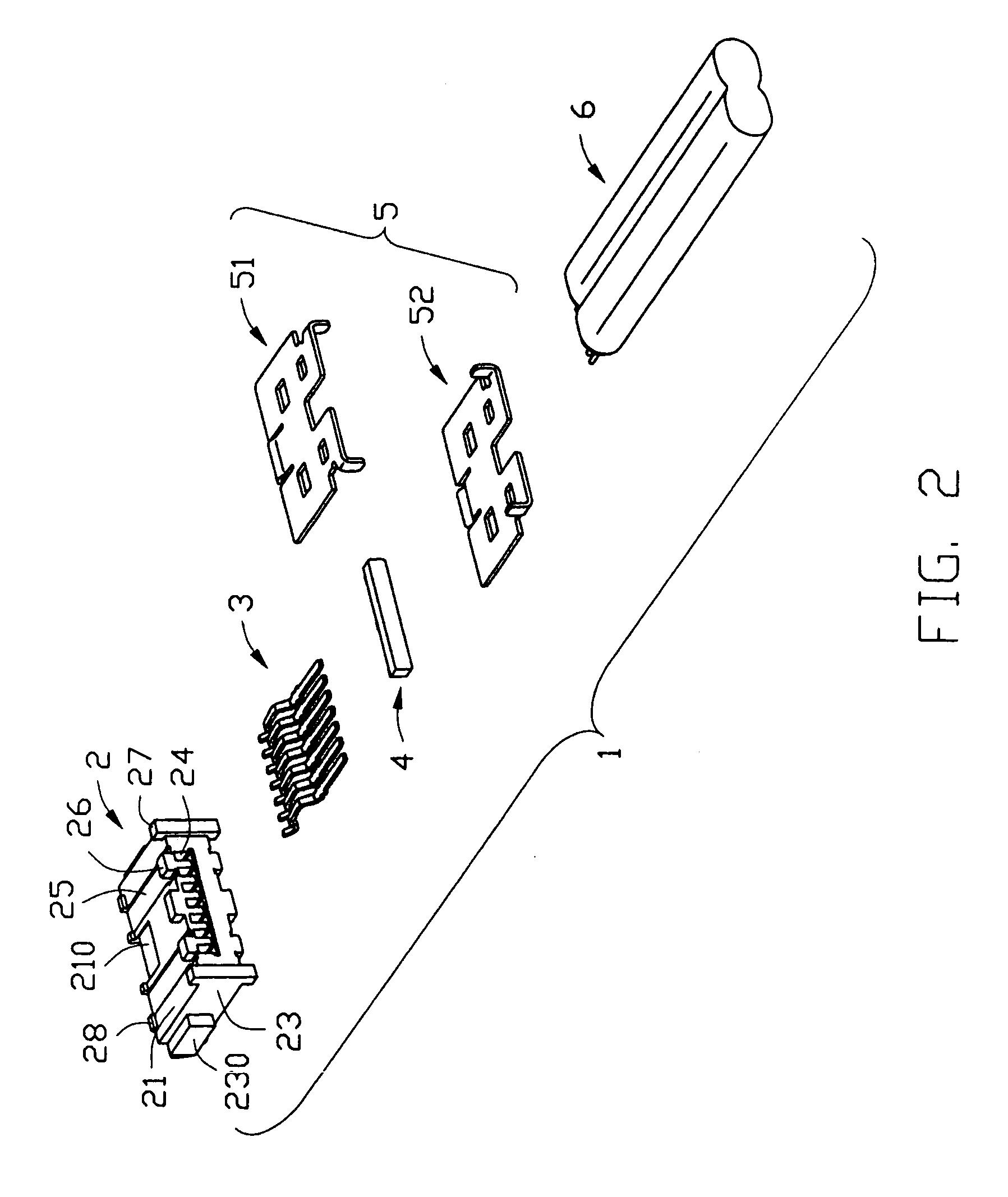
[0022]Referring to FIGS. 1–2 in conjunction with FIGS. 7–9, a cable end connector assembly 1 in accordance with the present invention comprises an insulative housing 2, a plurality of contacts 3, a spacer 4, a shielding member 5, a cable 6 and an insulative cover 7.

[0023]Referring to FIGS. 1–2, the insulative housing 2 comprises a relatively thicker upper wall 21, a relatively thinner lower wall 22 opposite to the upper wall 21 and a pair of sidewalls 23 connecting with the upper and the lower walls 21, 22. A rectangular receiving space 20 is circumscribed by the upper wall 21, the lower wall 22 and the sidewalls 23. A plurality of passageways 24 is defined forwardly from a rear face of the housing 2 and extends in the upper wall 21. A rectangular depression 210 is defined in a front middle portion of the upper wall 21 and a rectangular cutout 220 is defined in a front middle portion of the lower walls 22 corresponding to the depression 210. Each of the upper and the lower walls 21,...


PUM


Abstract

A cable end connector assembly (1) includes an insulative housing (2), a number of contacts (3) assembled to the insulative housing in a back-to-front direction, a shielding member (5) assembled to the insulative housing, a cable (6) including a number of signal conductors (62) and drain wires (64) respectively soldered with the contacts, and an insulative cover (7) over-molding rear portions of the insulative housing and the shielding member and a front end of the cable. The housing includes an upper wall (21), a lower wall (22) and a pair of sidewalls (23) connecting with the upper and the lower walls. The shielding member includes a first and a second shielding halves (51, 52) respectively attached to the upper wall and the lower wall of the insulative housing.

Description

BACKGROUND OF THE INVENTION[0001]1. Field of the Invention[0002]The present invention relates to a cable end connector assembly, and particularly to a shielded cable end connector assembly.[0003]2. Description of Related Art[0004]Serial ATA is an evolutionary replacement of the parallel ATA storage interface in the desktop as well as the cost-sensitive server and network storage market segments. The specification of Serial ATA allows for thinner, more flexible cables and lower pin counts. A conventional Serial ATA connector assembly comprises an insulative housing defining an L-shaped receiving space, a plurality of contacts received in the housing with tail portions exposed beyond the housing, a cable having a plurality of signal conductors and grounding drain wires respectively soldered with the tail portions of the contacts, and an insulative cover over-molded with a rear end of the housing. The cable for signal transmission comprises twin axial or parallel pair subassemblies. Ea...

Claims


Application Information

Patent Timeline
IPC IPC(8): H01R12/24H01R12/00H01R13/658
CPCH01R13/65807H01R13/6593H01R2107/00H01R24/562
Inventor SPINK, JR., WILLIAM E.
Owner HON HAI PRECISION IND CO LTD
Learn More