
Curtain blind take-up drive mechanism with non-slip effect

a technology of drive mechanism and blind, which is applied in the field of blind take-up drive mechanism with non-slip effect, can solve the problems of slats slipping downwards, idling situation, ineffective non-slip mechanism, etc., and achieve the effect of facilitating freehand operation

Inactive Publication Date: 2005-06-28
HUANG SHIEN TE
View PDF9 Cites 28 Cited by
  • Summary
  • Abstract
  • Description
  • Claims
  • Application Information

AI Technical Summary

Benefits of technology

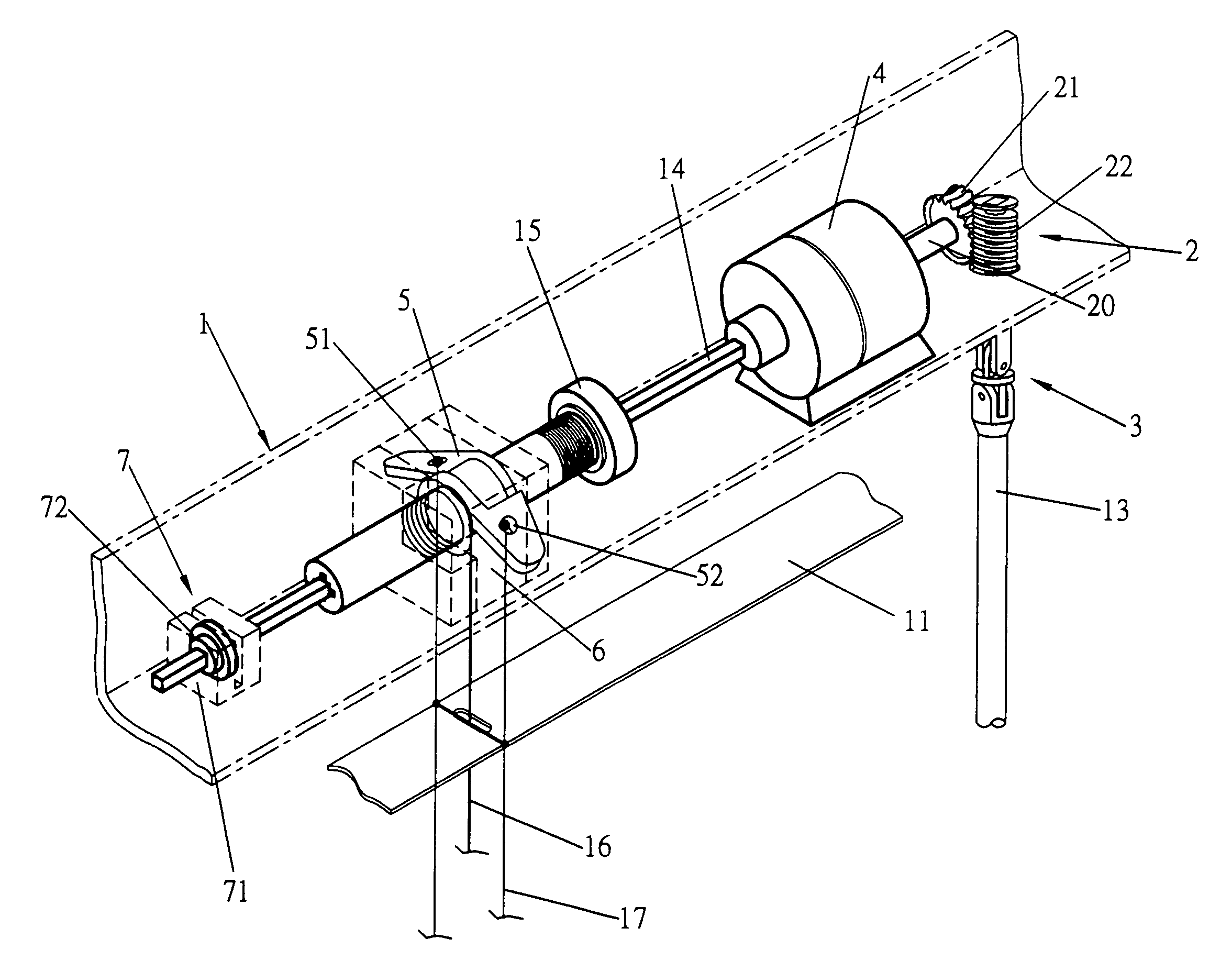
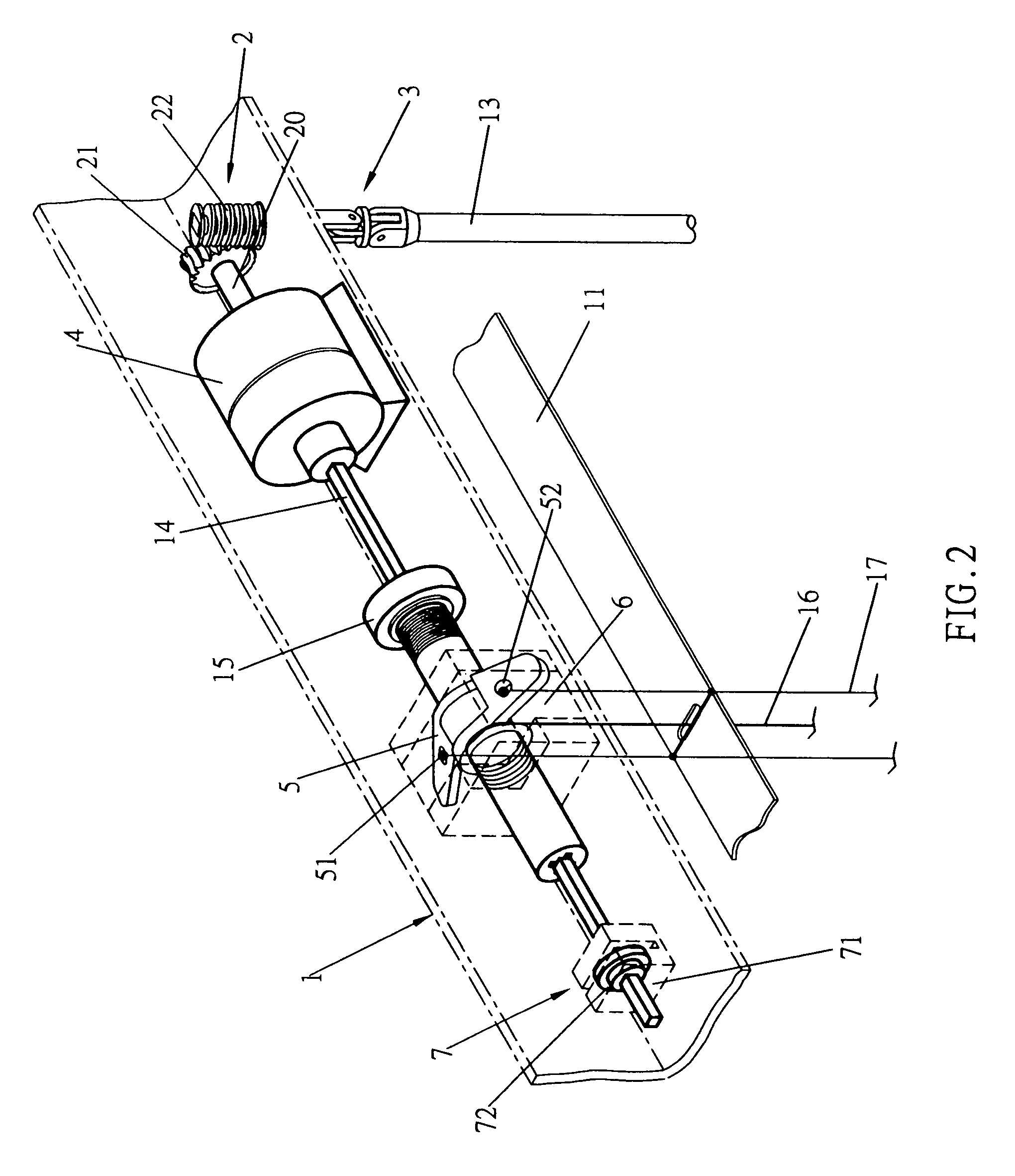
[0007]Regarding the aforementioned shortcomings, a power end of a drive shaft 14 of the present invention is configured to utilize a gear meshing method between a worm 22 and a worm gear 21, whereupon rotational speed is amplified through a transmission amplifier 4, allowing a reel 15 to achieve an amplified rotational speed when taking-up the slats, and thereby facilitating freehand operation of a slat tilt rod 13. A design objective of the present invention is to produce a return force actuated by teeth meshing and teeth surface pressure between the worm gear 21 and the worm 22, and forming thereof a radial designated effect on the worm gear 21, thereby achieving a non-slip effect, facilitating freehand operation and preventing danger from a lift cord of the prior art as described above.
[0009]A third objective of the present invention is to configure the transmission amplifier to utilize an inner-gear meshing configuration, which provides a design that is simple, easy and facilitating structurally change.
[0010]A fourth objective of the present invention is to configure the transmission amplifier to utilize a combinatory configuration of meshing gears to facilitate selectivity in transmission variation.

Problems solved by technology

However, the aforesaid non-slip mechanisms are ineffective, for instance, resilience under certain conditions or undulations of indeterminate external forces will likewise cause the slats to slip downwards.
Moreover, design of a unilateral ratchet clasp requires a frictional force to actuate a holding mechanism, and because cut-in angles or disparate strength of frictional forces, the frictional force often results in an idling situation arising.
More importantly, when wind power blows the blind slats, force of traction is produced, and dragging down of the slats results thereof.

Method used


Image

  • Curtain blind take-up drive mechanism with non-slip effect
  • Curtain blind take-up drive mechanism with non-slip effect
  • Curtain blind take-up drive mechanism with non-slip effect

Examples


Embodiment Construction

[0023]Referring to FIGS. 2 and 2-1, which show a non-slip mechanism of the present invention comprising a worm gear unit 2 that avails the service of a transmission amplifier 4 to achieve high speed taking-up of slats 11, and utilizes a high rotational slippage between a worm gear 21 and a worm 22 to actuate meshing of surfaces of gear teeth and thereof a reverse direction stoppage surface pressure, thereby producing a reverse direction stoppage effect, and achieving the objective of averting the slats 11 from slipping down under their own weight or from external forces.

[0024]An operating end comprises a design employing a slat tilt rod 13, the slat tilt rod 13 is adapted to accomplish a safety objective, whereby usage of a pull cord in prior art designs can result in entangling with limbs and thereof resulting in a dangerous situation arising.

[0025]A primary configuration of the present invention comprises a drive shaft 14 configured lengthwise within a head rail 1. The drive shaft...


PUM


Abstract

A curtain blind take-up drive mechanism with non-slip effect having a freehand turn operation. The non-slip effect is configured to prevent slats of the blind from slipping down, and further includes coupling a power end of a drive shaft to a reel. The drive shaft connects to a worm gear via a transmission amplifier. The worm gear is actuated through reciprocally engaging with a worm driven via a flexible shaft coupling and through operation of a slat tilt rod. Reciprocal teeth meshing and teeth surface pressure between the worm gear and the worm achieves a high slip-rate, and thereby inhibits reverse transmission, thus accomplishing a reverse direction stoppage effect, and further producing a large frictional force and forming a surface-pressure slip effect thereof. The transmission amplifier allows the drive shaft to achieve a high rotational speed, thereby facilitating freehand operation for taking-up and letting-down of the slats.

Description

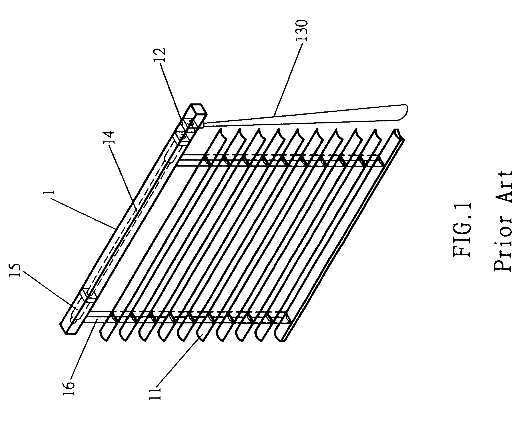
BACKGROUND OF THE INVENTION[0001](a) Field of the Invention[0002]The present invention relates to curtain blinds, and more particularly to a curtain blind take-up drive mechanism with non-slip effect, providing freehand turn operation. The non-slip effect is further configured to prevent slats of the blind from slipping down under their own weight.[0003](b) Description of the Prior Art[0004]Referring to FIG. 1, which shows a schematic view of a Venetian blind, including a head rail 1 lengthwise configured with a drive shaft 14 therein. A reel 15 is respectively attached to both right and left ends of the drive shaft 14. A power end is actuated through any transmission of a turntable drive unit 12. Indirect operation of a lift cord 130 actuates the reels 15, and thereof reel cords 16 are enabled to take-up or let-down slats 11. Upon a plurality of the salts 11 of a prior Venetian blind coming together, the slats 11 thereupon form a specific synergistic weight with proportional downwa...

Claims


Application Information

Patent Timeline
Patent Type & Authority Patents(United States)
IPC IPC(8): E06B9/322E06B9/28
CPCE06B9/322
Inventor HUANG, SHIEN-TE
Owner HUANG SHIEN TE
Learn More