
Connector scheme to allow physical orientation of a computer peripheral

a technology of connecting scheme and peripheral, which is applied in the direction of electrical discharge lamps, coupling device connections, instruments, etc., can solve the problems of not being able to connect directly to the computer by attaching cable, the interface of older and traditional peripheral devices is no longer fast enough for the modern peripheral, and the problem of affecting the physical orientation of the peripheral device, etc., to achieve the effect of facilitating the peripheral orientation

Inactive Publication Date: 2005-06-21
HEWLETT PACKARD DEV CO LP
View PDF11 Cites 74 Cited by
  • Summary
  • Abstract
  • Description
  • Claims
  • Application Information

AI Technical Summary

Benefits of technology

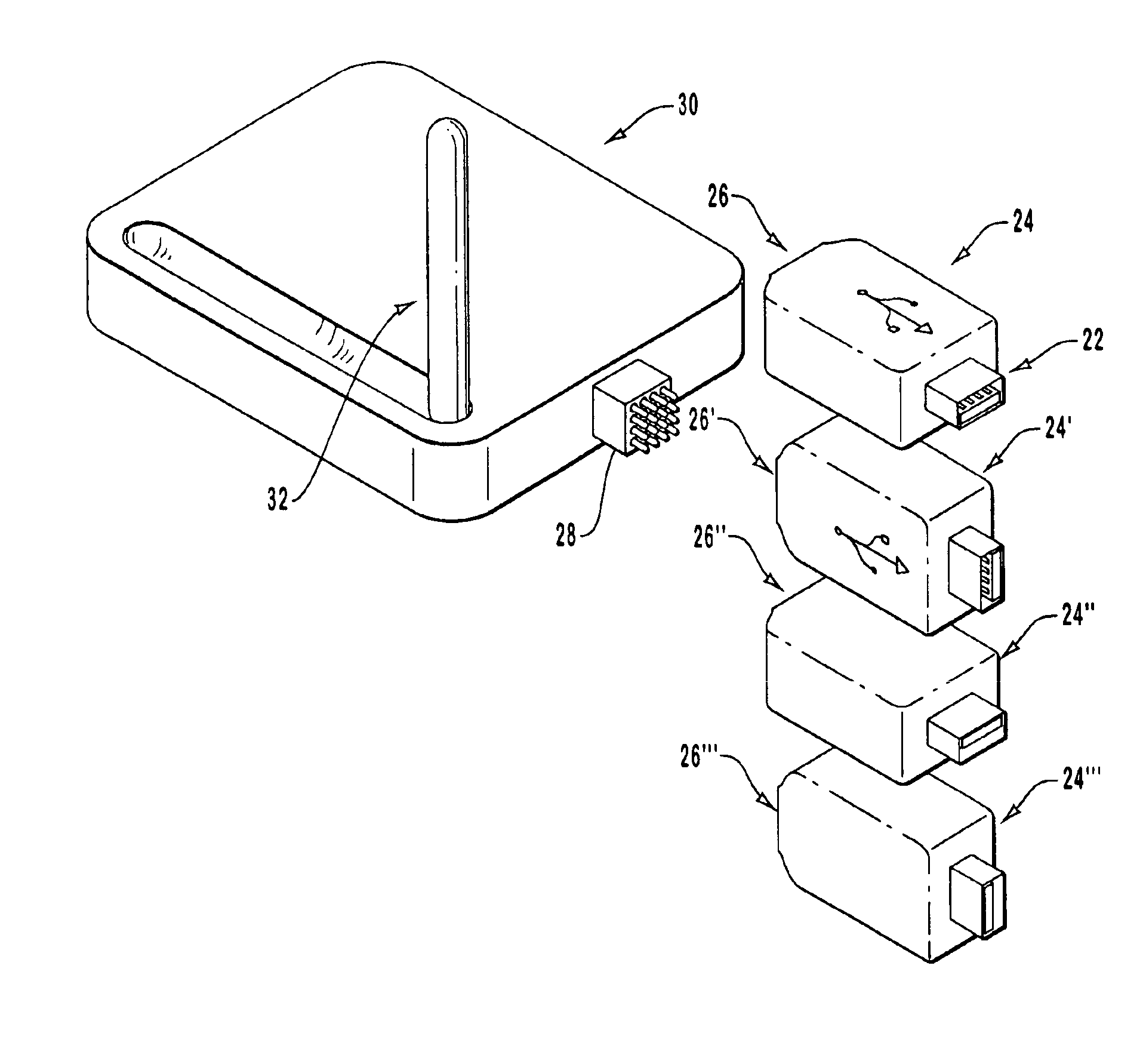
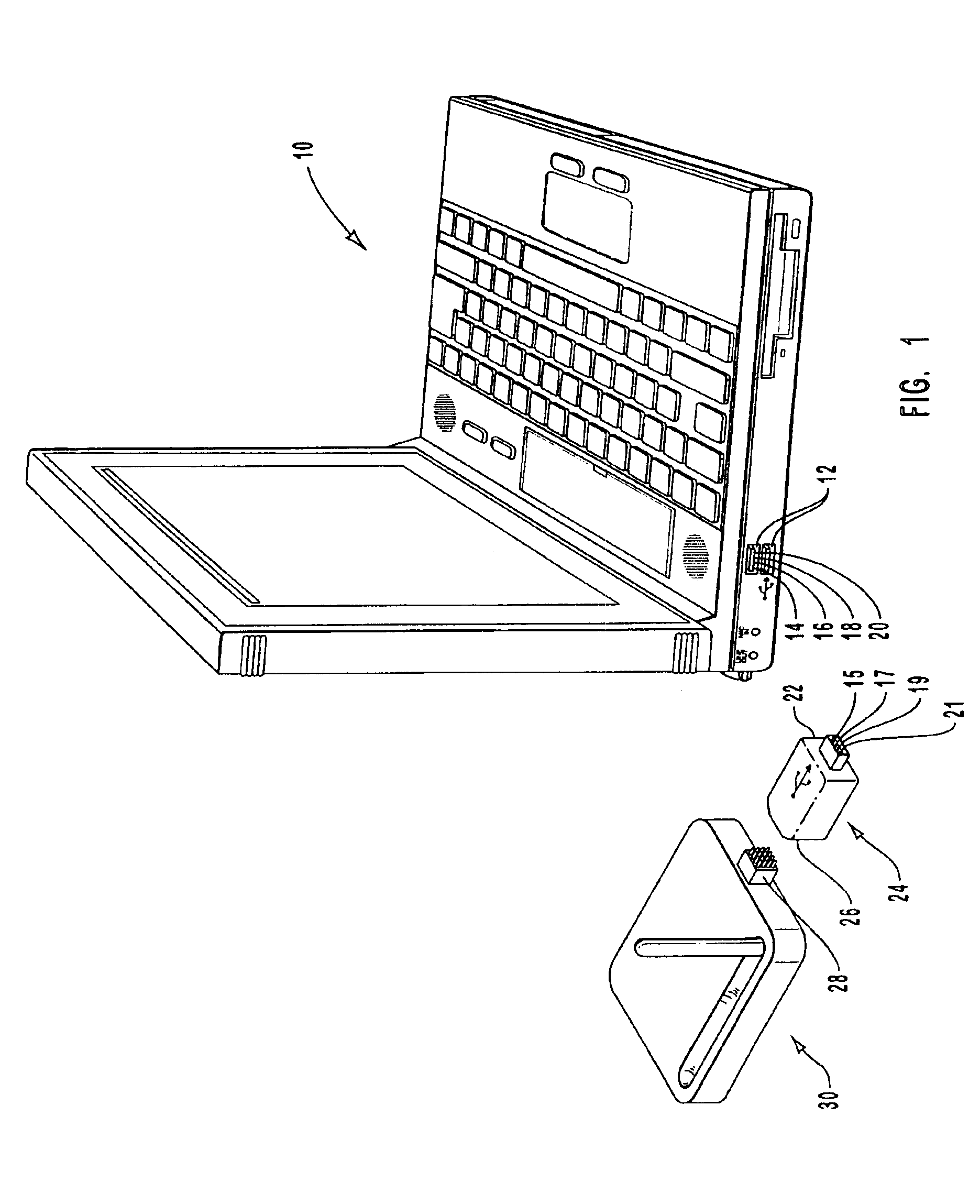
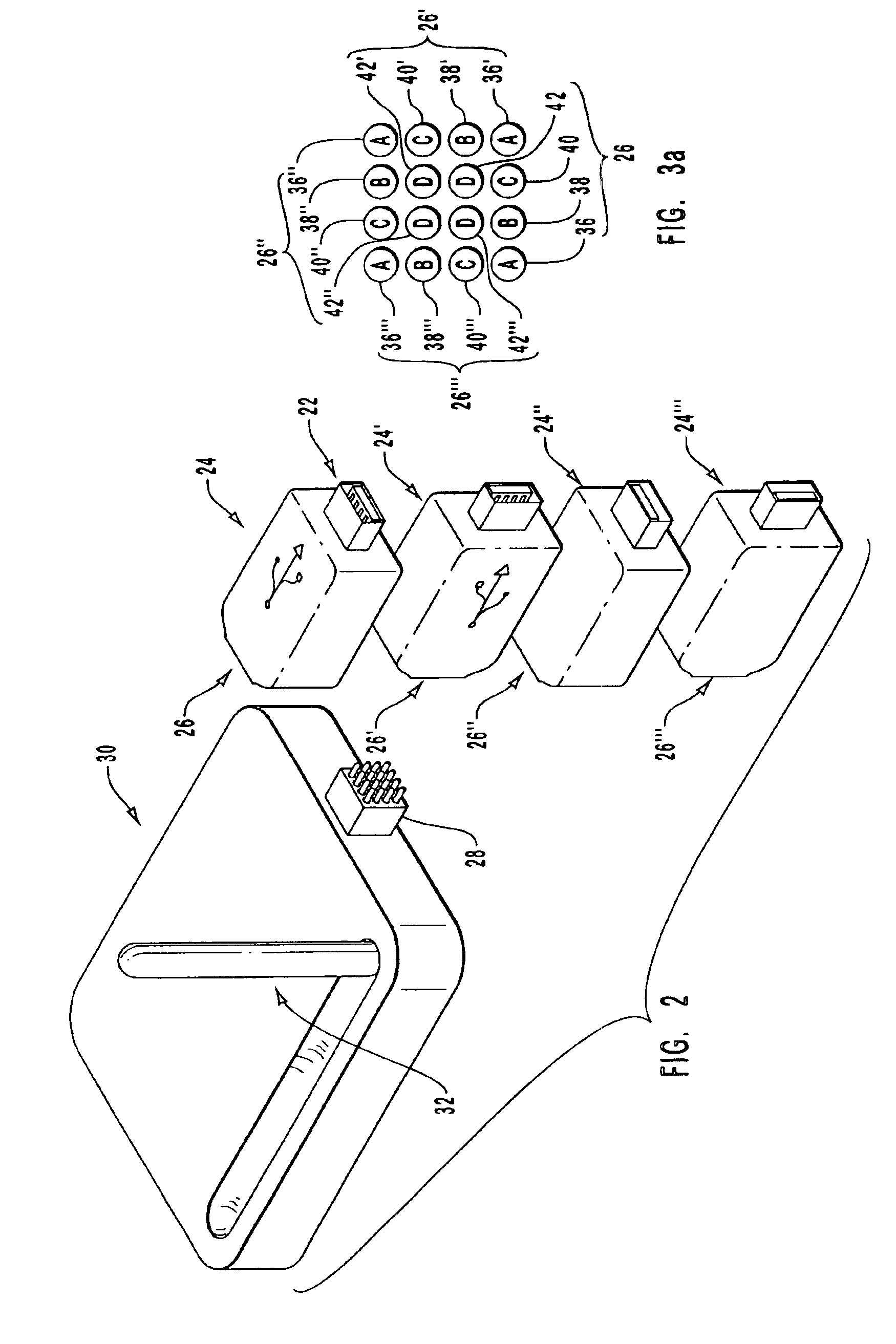
[0013]The present invention creates a communication quality connection across an interface between a digital device and a peripheral device, while enabling the flexible orientation of the peripheral device relative to the interface. These qualities are primarily accomplished through an adaptor, which includes two connectors one for coupling to the digital device and a second connector for coupling to the peripheral device. The adaptor electrically extends the interface signals to the second connector, which facilitates peripheral orientation.
[0015]Accordingly, one aspect of the apparatus is to provide a simple, reliable, and low cost solution to directly connecting the peripheral to the USB connector receptacle while maintaining a desired peripheral orientation. Other solutions, which may be available, compromise one of these elements.
[0017]Yet another aspect of the apparatus is to create a USB compatible short-range wireless (e.g. “Bluetooth”, 802.11 RF, etc.) interface device that properly orients the antenna and maintains all of the traditional wireless functionality. The USB connection improves the connection speed between the peripheral and host computer, thereby improving the overall wireless connections available.

Problems solved by technology

Adding an old-fashioned peripheral device to a digital device, such as a personal computer, can be a very difficult process.
Unfortunately, as computer processor speeds and user performance expectations continue to increase, it is apparent that the older and traditional peripheral device interfaces no longer communicate at fast enough rates for the modern peripherals.
Unfortunately, both types of connectors have a fixed orientation with respect to the receptacles for receiving the plugs on the host and peripheral device.
One common problem presently faced by many USB peripheral devices is how to attach a peripheral, which requires a specific orientation, via a USB plug to a USB receptacle in each of the possible orientations without using multiple joints or a cable to reorient the peripheral.
Unfortunately, the attached cable solution does not allow direct connection to the computer, as a finite length of cable is necessary before it can reorient the peripheral, and thus the cable retains a residual amount of rotational tension.
The use of multiple joints is also undesirable as these connections are expensive and not reliable.
Conventional antennas used to connect a digital device to a wireless communication system or cellular telephone are typically placed externally from the digital device because of the noise, interference, obstruction and shielding caused by the various components of the digital device.
In particular, conventional antennas do not function correctly if they are obstructed or shielded by the housing or other structures of the digital device.
However, the use of multiple joints or a cable hinders the performance of the USB antenna by reducing the available power for radiation.

Method used


Image

  • Connector scheme to allow physical orientation of a computer peripheral
  • Connector scheme to allow physical orientation of a computer peripheral
  • Connector scheme to allow physical orientation of a computer peripheral

Examples


Embodiment Construction

[0026]FIG. 1 and the following discussion are intended to provide a brief, general description of a suitable computing environment in which the invention may be implemented. Those skilled in the art will appreciate that the invention may be practiced with many types of computer system configurations, including personal computers, hand-held devices, multi-processor systems, microprocessor-based or programmable consumer electronics, network PCs, minicomputers, mainframe computers, Personal Digital Assistants, digital cameras, and the like.

[0027]Reference is first made to FIG. 1, an exemplary laptop computer system or environment in which the present invention may be utilized or implemented. FIG. 1 is intended to be illustrative of potential systems that may utilize the present invention and is not to be construed as limiting. The system of FIG. 1 illustrates a portable computer 10 having a pair of universal serial bus (USB) series “A” connector receptacles 12 that are each configured ...


PUM


Abstract

An adapter mechanism for facilitating re-orientation of a plug having an original orientation that is unsuitable for a peripheral device is presented. Re-orientation of a peripheral device is possible in an embodiment by advancing a symmetrical interface to another mating position exhibiting a hospitable orientation. An adaptor maintains USB functionality while providing the ability to reorient a fixedly attached peripheral. The adaptor mechanism also allows a USB wireless peripheral device with an antenna to plug directly into the USB receptacle connector on a digital device while orienting the antenna upwards to improve the quality of the transmitted and received signals.

Description

BACKGROUND OF THE INVENTION[0001]1. Field of the Invention[0002]The present invention relates generally to adaptor structures selectively coupled to an interface on a digital device. More specifically, the present invention applies to an adaptor for directly coupling to a peripheral device and selectively coupling to a digital device regardless of the digital device's interface orientation or position.[0003]2. Description of Related Art[0004]Adding an old-fashioned peripheral device to a digital device, such as a personal computer, can be a very difficult process. The user is often required not only to have considerable computer expertise, but also a certain amount of providence. First, the user must determine which port from a vast assortment of possibilities on the digital device to use. Then in most cases, the user must open the digital device to install a peripheral device controller card and set various DIP switches. Finally, the user must properly configure the touchy IRQ sett...

Claims


Application Information

Patent Timeline
IPC IPC(8): H01R31/06G06F1/16
CPCH01R31/06G06F1/1632
Inventor MORLEY, KENNETH S.CHRISTENSEN, SCOTT M.
Owner HEWLETT PACKARD DEV CO LP
Learn More