
Dynamically sensitized decorative lighting equipment

a lighting equipment and sensitization technology, applied in the direction of lighting and heating equipment, lighting support devices, coupling device connections, etc., can solve the problems of difficult configuration of ropes, monotonous adjacent lamps, inability to fully achieve sensitization effect, etc., and achieve unique and appealing lighting effects

Inactive Publication Date: 2005-06-21
CHEN JOHNNY
View PDF6 Cites 53 Cited by
  • Summary
  • Abstract
  • Description
  • Claims
  • Application Information

AI Technical Summary

Benefits of technology

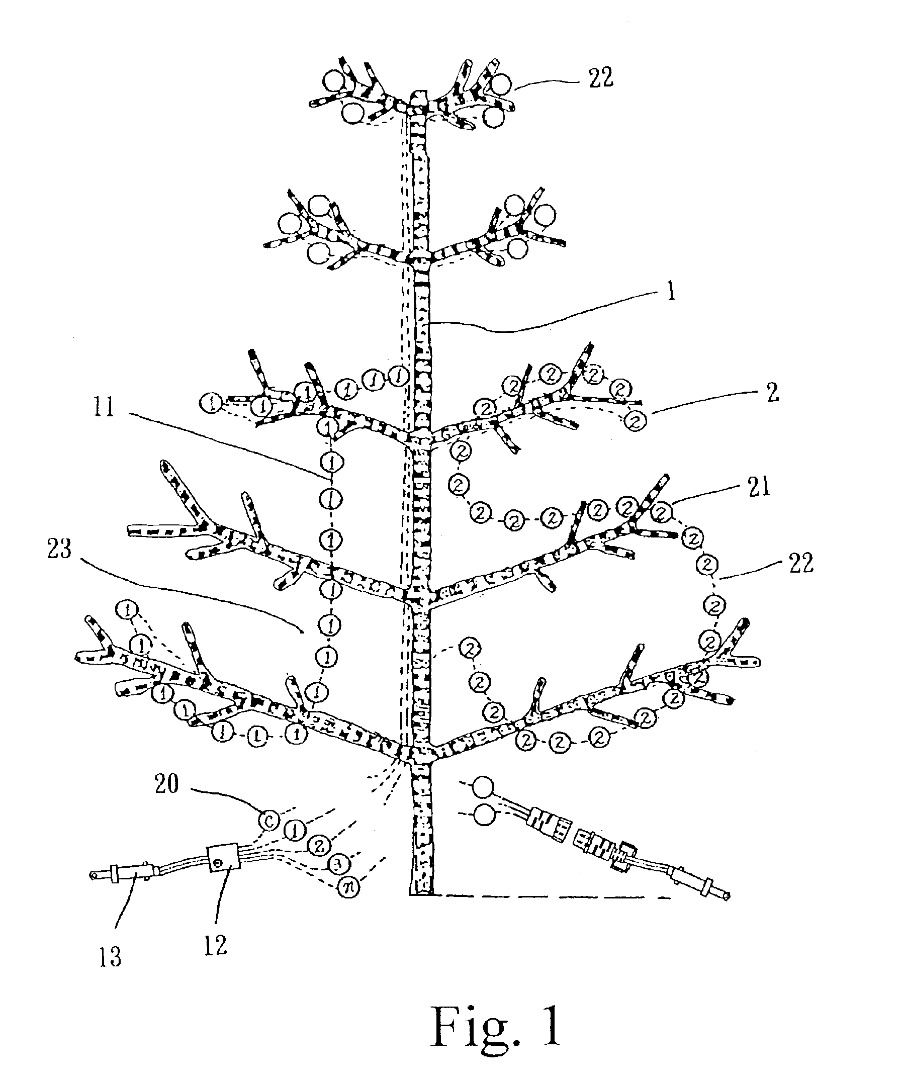
[0005]For rectifying the aforesaid disadvantages inherent to the conventional technique for decorative lighting, an object of the present invention is to provide a decorative lighting equipment which can be configurated into specially unique patterns of various artistic contours by hanging plurality of miniature lamps or LEDs on a preformed structural framework so as to attain an unique and appealing lighting effect.
[0006]Another object of the present invention is to provide a decorative lighting equipment that a plurality of miniature lamps or LEDs is divided in several groups to glitter alternatively one after another or keep constantly turning on according to individual controls so as to reduce the capacity of the unit controller size and the conductor size as well.

Problems solved by technology

In bygone time, marvelous sensitization effect cannot be fully attained owing to limited capacity of unit controller and a power circuit that restricts amount of lamps allowable to be installed thereof.
The conventional decorative lighting which is usually hanging a plurality of miniature lamps on trees or along extended ropes and glittering alternatively the adjacent lamps is too monotonous.
Besides, the trees and ropes are difficult to be configurated into a desired contour, and for lighting a large area using a lot of lamps, a large controller and a big conductor size is required which calls for expensive installation cost.

Method used


Image

  • Dynamically sensitized decorative lighting equipment
  • Dynamically sensitized decorative lighting equipment
  • Dynamically sensitized decorative lighting equipment

Examples


second embodiment

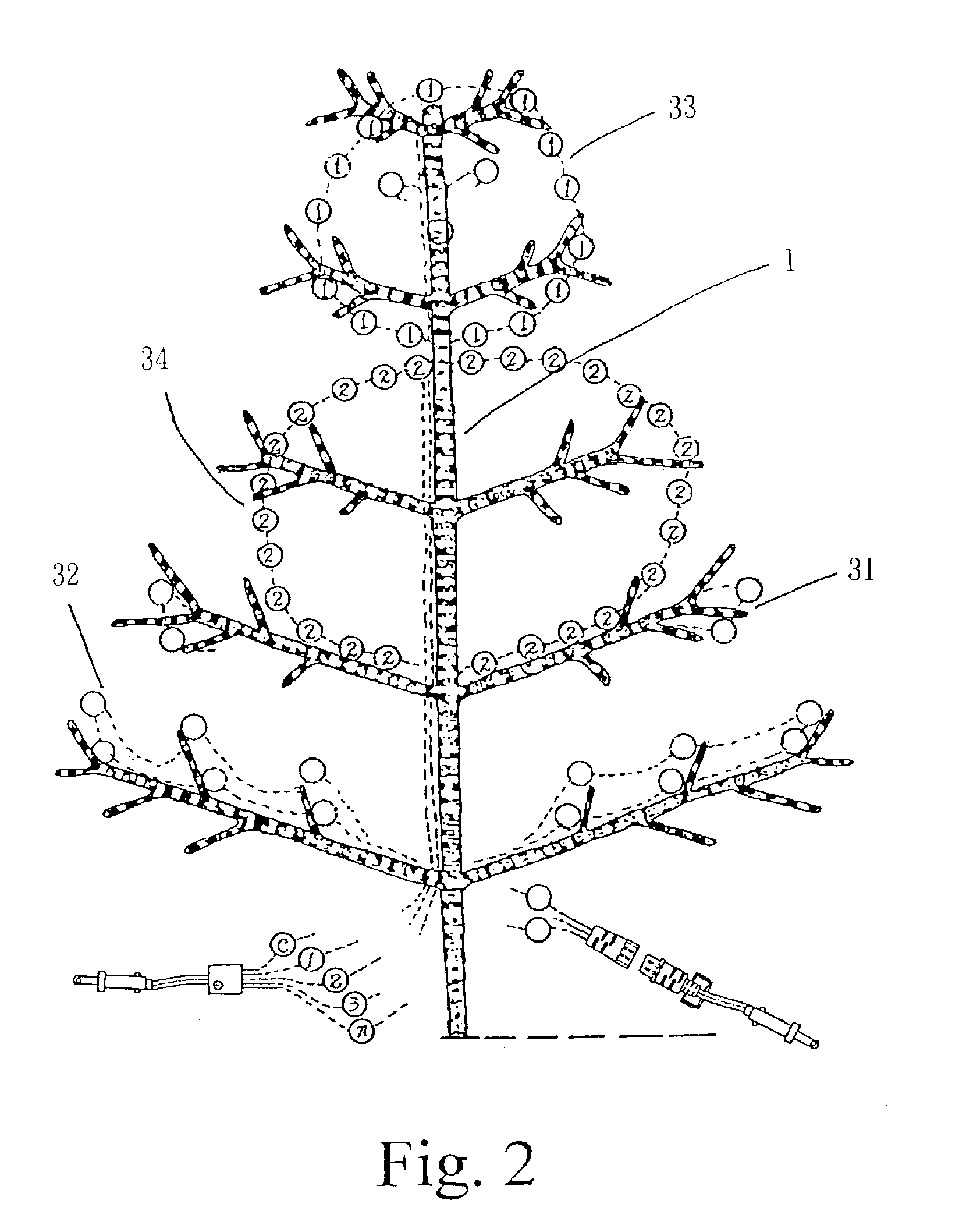
[0022]In the second embodiment shown in FIG. 2, two constantly turned on lamp groups 31, 32 are installed at two lower sides of the framework 1 with each occupying one side, while two alternatively glittering lamp groups 33, 34 are installed on upper portion of the framework 1 to form a round snowman figure. All lamp groups 31, 32, 33, 34 are connected to a gang controller 13.

third embodiment

[0023]In the third embodiment shown in FIG. 3, constantly turned on lamp groups 41, 42, 43 are stacked up like ladder stages at the lower portion of the framework 1, while two cordial shaped alternatively glittering lamp groups 44, 45 are occupying respectively the top and the middle portions thereof.

fourth embodiment

[0024]In the fourth embodiment shown in FIG. 4, a Δ shaped constantly, turned on lamp groups 51 and a Δ shaped glittering lamp groups 52 are disposed along the twigs of the tree-shaped framework 1 in the manner each group occupies outerside and innerside of right and left twigs alternatively so that the whole structure may look like a waving wand when the lamp groups are energized.


PUM


Abstract

Disclosed is a dynamically sensitized decorative lighting equipment wherein a plurality of lighting elements such as miniature decorative lamps or LEDs is divided in several individual groups which are hung on a structural framework and configurated into special patterns of variety of artistic contours to exhibit a unique and dynamical sensitization lighting effect by partially constantly turning on and partially alternatively glittering.

Description

BACKGROUND OF THE INVENTION[0001]1. Field of the Invention[0002]The present invention relates to decorative lighting equipment, and in particular, to a plurality of lighting elements such as miniature decorative lamps divided in several individual groups which are hung on a structural framework and configurated into special patterns of various artistic contours to exhibit a unique and dynamical sensitization lighting effect.[0003]2. Description of the Prior Art[0004]Glittering miniature lamps are favorite decorative articles in festival occasions and Christmas time, or for patio and garden lighting, and also applicable for advertisement. In bygone time, marvelous sensitization effect cannot be fully attained owing to limited capacity of unit controller and a power circuit that restricts amount of lamps allowable to be installed thereof. The conventional decorative lighting which is usually hanging a plurality of miniature lamps on trees or along extended ropes and glittering alterna...

Claims


Application Information

Patent Timeline
IPC IPC(8): A47G33/00A47G33/06F21S4/00F21V23/00F21V23/06
CPCA47G33/06F21S4/001F21V23/00Y10S362/806F21W2121/04F21Y2101/02F21V23/06F21Y2101/00F21S4/10F21Y2115/10
Inventor WU, JENG-SHYONG
Owner CHEN JOHNNY
Learn More