
Ultrasonic flow-measuring method

a technology of ultrasonic flow and measuring method, which is applied in the direction of volume flow measuring device, liquid/fluent solid measurement, and dynamic fluid flow effect of volume/mass flow, etc. it can solve the problems of insufficient dead-time correction, possible factoring, and inability to accurately determine the dead time. , to achieve the effect of precise determination of the dead tim

Inactive Publication Date: 2005-06-14
KRONE GMBH
View PDF16 Cites 34 Cited by
  • Summary
  • Abstract
  • Description
  • Claims
  • Application Information

AI Technical Summary

Benefits of technology

[0010]It is therefore the objective of this present invention to introduce an ultrasonic flow-measuring method that ensures a very precise determination of the dead time, which, in turn, permits an exact-as-possible determination of the flow rate.
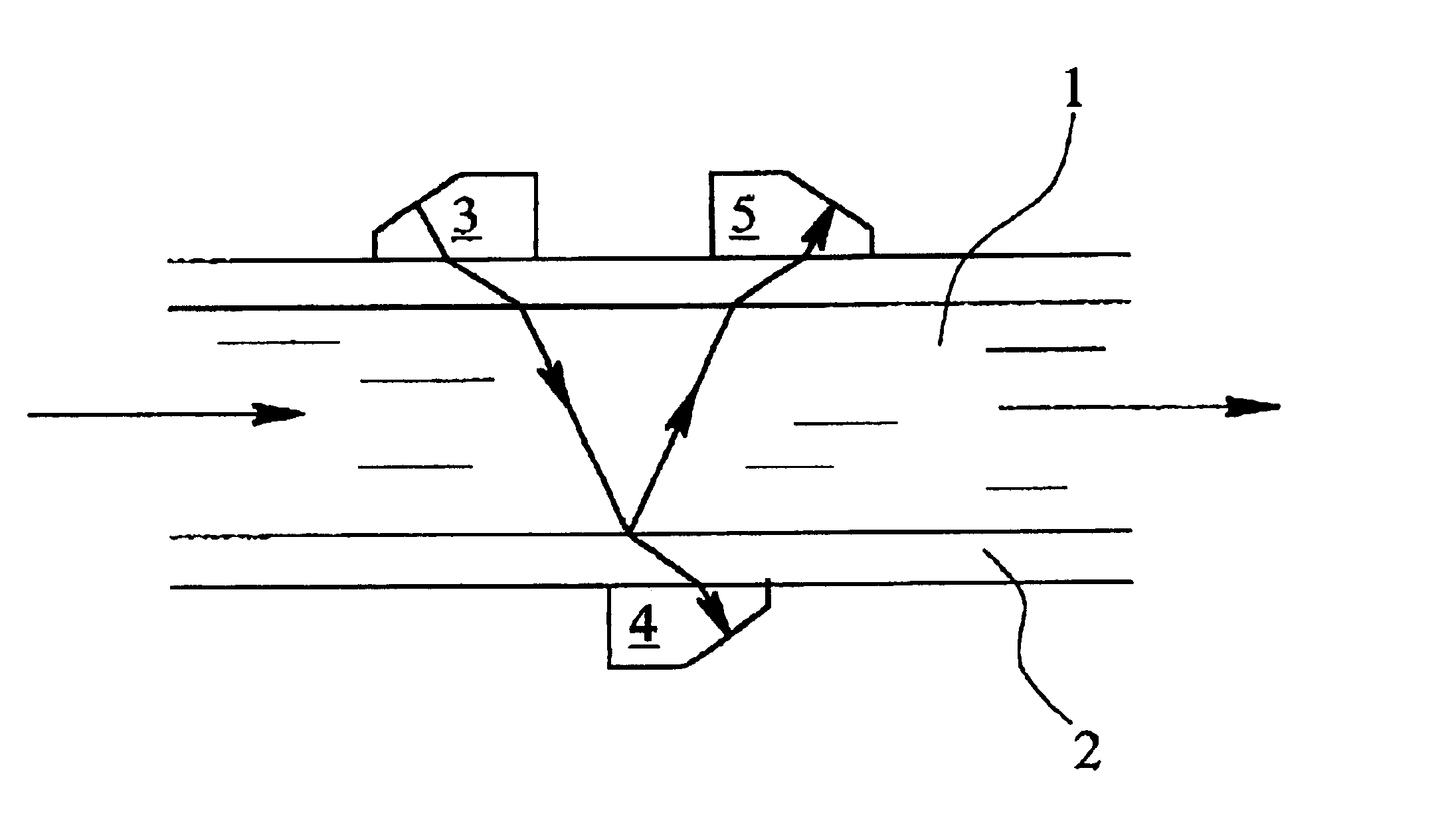
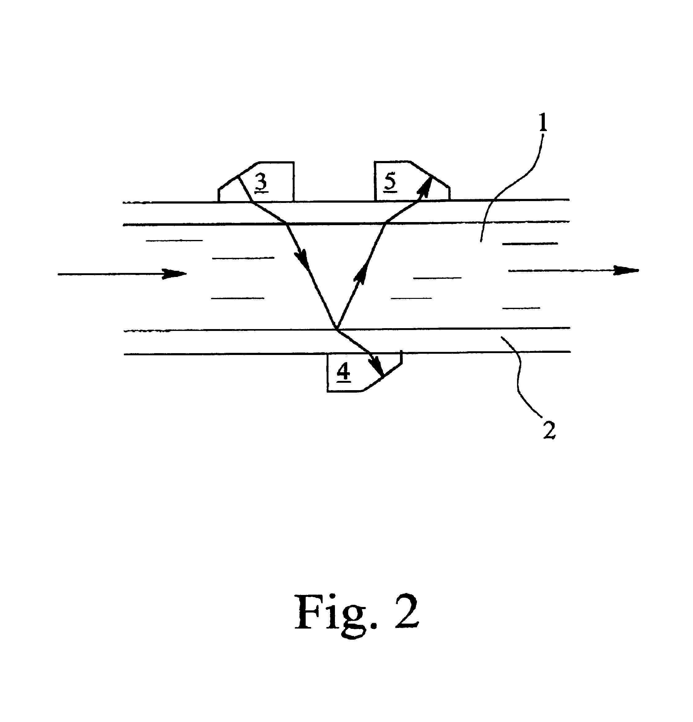
[0018]In an alternative, preferred embodiment of the invention, at least three ultrasonic transducers are so spaced and offset relative to one another that the ultrasonic signal is transmitted from a first transducer along the predefined path with a predefined length and at a predefined angle relative to the flow direction and is received by a second transducer, the ultrasonic signal is partly reflected off the line in the area of the second transducer and then travels along the predefined path with the predefined length and at the predefined angle relative to the flow direction to the third ultrasonic transducer, and the runtime of the ultrasonic signal from the first transducer to the second transducer and the runtime of the ultrasonic signal from the first transducer to the third transducer are measured and the dead time of the ultrasonic flow-measuring process is calculated based on the difference between twice the runtime of the ultrasonic signal from the first transducer to the second transducer and the single runtime of the ultrasonic signal from the first transducer to the third transducer. This preferred embodiment of the invention allows for a very efficient configuration of the ultrasonic transducers that can also be easily implemented especially in a clamp-on ultrasonic flowmeter.
[0020]In a preferred implementation of the invention, however, the dead time of the ultrasonic flow-measuring process is determined in a real-time operation and is preferably applied in the determination of the flow rate of the flowing medium, again, in real time. An appropriate real-time operation is made possible by virtue of the simple applicability of the method according to this invention, with the real-time compensation for the dead time resulting in an optimal correction of the measured flow rate and thus in the most precise measuring results.

Problems solved by technology

In practice, however, it has been found that the measurements obtained have in part been rather error-prone since during the measuring operation the dead time does not remain constant at all but tends to change.
However, these approaches do not make it possible to factor-in the effects that cause dead-time variations or that originate in the flowing medium itself, so that in the final analysis dead-time correction remains inadequate.

Method used


Image

  • Ultrasonic flow-measuring method
  • Ultrasonic flow-measuring method
  • Ultrasonic flow-measuring method

Examples


Embodiment Construction

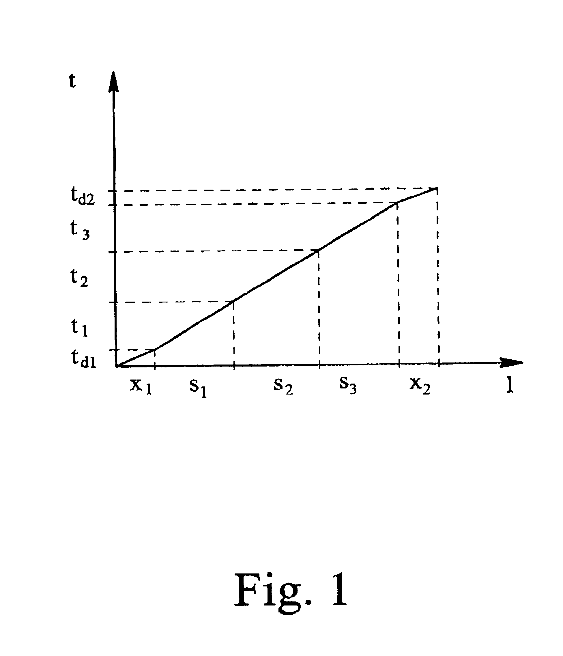
[0025]Plotted in FIG. 1 is the time t taken by the ultrasonic signal to pass through a given path as a function of the respective path length l. x1 and x2 indicate the propagation path lengths in the two ultrasonic transducers between which the ultrasonic signal travels through the flowing medium, with td1 and td2 representing the corresponding runtimes including the delay in the measuring electronics. The sum of these two times td1 and td2 equals the dead time td.

[0026]In addition, s1, s2 and s3 represent immediately consecutive, identical path segments with a predefined length and a predefined angle relative to the direction of flow. Corresponding identical path segments may extend as illustrated in FIG. 2 which figure shows only two consecutive segments. The runtimes of the ultrasonic signal for these path segments are identified by t1, t2 and t3.

[0027]To determine the combined dead times of the ultrasonic flow-measuring process, a preferred embodiment of the invention employs fo...


PUM


Abstract

An ultrasonic flow-measuring method determines the flow rate of a medium flowing through a line is determined by measuring the runtime of an ultrasonic signal that travels from a first ultrasonic transducer to at least one other ultrasonic transducer. The runtime of the ultrasonic signal as it makes m passes in immediate succession through a predefined path over a predefined path length and at a predefined angle relative to the flow direction is measured, and the runtime of the ultrasonic signal as it makes n passes in immediate succession through the predefined path over the predefined path length at the predefined angle relative to the flow direction is measured, with m and n being mutually different integers, and the dead time of the ultrasonic flow-measuring process is determined on the basis of the measured runtimes. This ultrasonic flow-measuring method permits real-time compensation for the dead time during the actual measuring process, the result being highly accurate measurements.

Description

[0001]This invention relates to an ultrasonic flow-measuring method whereby the flow rate of a medium flowing through a line is determined by measuring the runtime of an ultrasound signal traveling from a first ultrasound transducer to at least one other ultrasound transducer.BACKGROUND OF THE INVENTION[0002]1. Field of the Invention[0003]Ultrasonic flow-measuring processes have been implemented with the aid of ultrasonic flowmeters ranging in design from built-in versions all the way to flexible clamp-on systems (clamp-on ultrasonic flowmeters). Ultrasonic flowmeters are available for lines with diameters from a few millimeters to several meters and are typically employed for measuring the volumetric flow rate of low-viscosity mediums.[0004]The measuring concept in an ultrasonic flow-measuring process is based either on the entrainment effect or on the Doppler effect. The entrainment effect derives from the fact that the runtime of an ultrasound signal traveling through a flowing m...

Claims


Application Information

Patent Timeline
Patent Type & Authority Patents(United States)
IPC IPC(8): G01F1/66G01F15/02
CPCG01F15/024G01F1/667
Inventor MOLENAAR, MARCEL MEIJLOMVAN DIJK, EUGENE ALBERT
Owner KRONE GMBH
Learn More