
Photoreceptor drum and image forming apparatus

a technology of photoreceptor drum and image forming apparatus, which is applied in the direction of electrographic process apparatus, shafts and bearings, instruments, etc., can solve the problems of affecting the smooth rotation movement of the rotational wheel, unable to completely eliminate eccentricity, and unable to achieve the effect of eliminating eccentricity

Inactive Publication Date: 2005-06-14
SHARP KK
View PDF19 Cites 72 Cited by
  • Summary
  • Abstract
  • Description
  • Claims
  • Application Information

AI Technical Summary

Benefits of technology

[0009]It is an object of the present invention to provide a photoreceptor drum and an image forming apparatus which permit rotation driving force to be transmitted from the side of the driving section without the problem of jerky rotation movement, and which permit the rotation driving force to be transmitted to the unit which acts on the driving section without the problem of jerky rotation movement.

Problems solved by technology

Here, generation of jerky movement of the driving force transmission means for transmitting the driving force to the photoreceptor drum would be the problem.
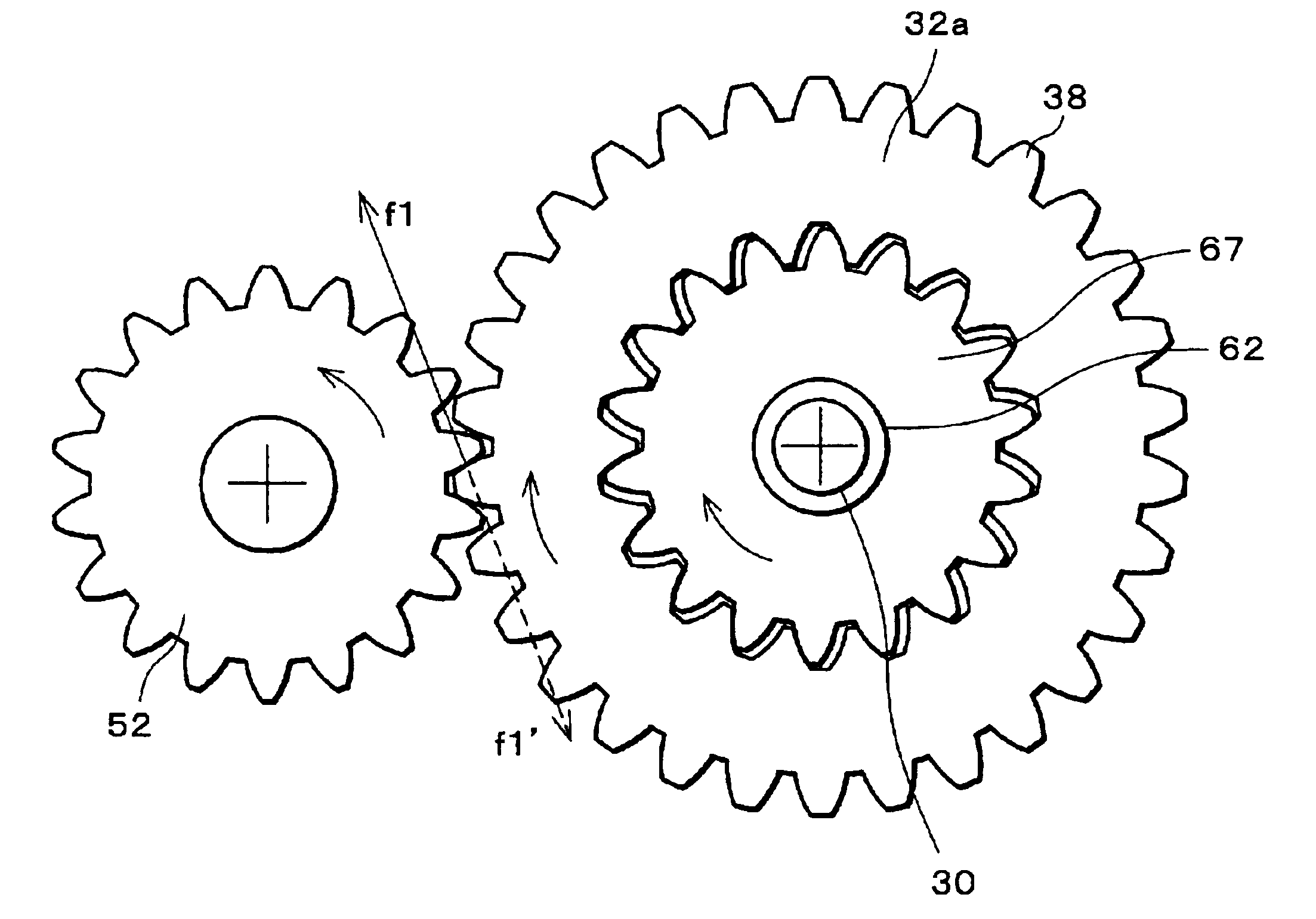
However, with the structure of the Japanese Unexamined Patent Publication No. 64-21466 / 1989, even if the drive section and the photoreceptor drum are manufactured with high precision, it would not be possible to completely eliminate eccentric error or axis deviation of gears in engagement, there is no win situation to eliminate such eccentricity or eccentric axis.
In this state, when the photoreceptor drum and the drive section are connected without generating jerky movement, for example, due to the excessive force exerted to the connected part, a force is exerted in the direction of disturbing stable engagement of the gears, which hinders smooth rotation movement.
Additionally, due to the taper provided at the connected part, a force is exerted in the direction of moving the photoreceptor drum in the axial direction, thereby presenting the problem that deviation of the photoreceptor drum in the axial direction is liable to occur periodically.
Therefore, a distance between the axes of the external gear and the internal gear is liable to change due to variations in load of the driving transmission, etc., thereby presenting the problem that stable rotation movement of the photoreceptor drum cannot be ensured.

Method used


Image

  • Photoreceptor drum and image forming apparatus
  • Photoreceptor drum and image forming apparatus
  • Photoreceptor drum and image forming apparatus

Examples


embodiment 1

[Embodiment 1]

[0083]Referring to FIGS. 1 through 10, the following description will explain one embodiment of the present invention.

[0084]FIG. 3 is an explanatory view illustrating the structure of a printer as an image forming apparatus in accordance with the present embodiment. This printer is arranged so as to form a color image on a predetermined sheet (recording sheet) based on image data as transmitted from an external section. As illustrated in FIG. 3, the printer of the present embodiment includes optical units 1a, 1b, 1c and 1d, developer units (process units) 2a, 2b, 2c and 2d, photoreceptor drums 3a, 3b, 3c and 3d, cleaning units 4a, 4b, 4c and 4d and chargers 5a, 5b, 5c and 5d, a transport belt unit 8, a fixing unit 12, a sheet transport path S, a feed tray 10, and a discharge tray 15.

[0085]The image data to be processed in the printer of the present embodiments correspond to color image in respective colors, i.e., black (K), cyan (C), magenta (M), and yellow (Y). Theref...


PUM


Abstract

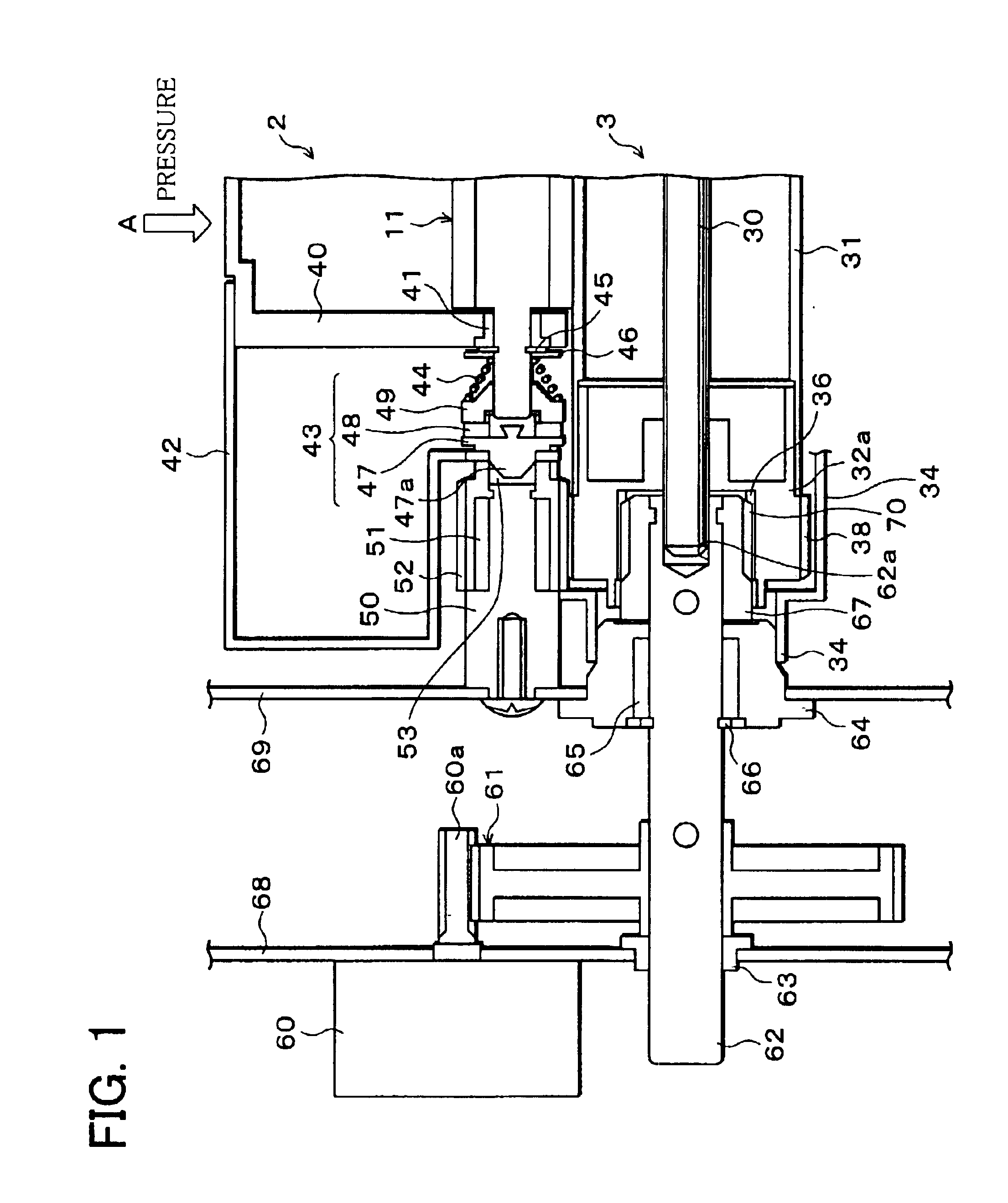
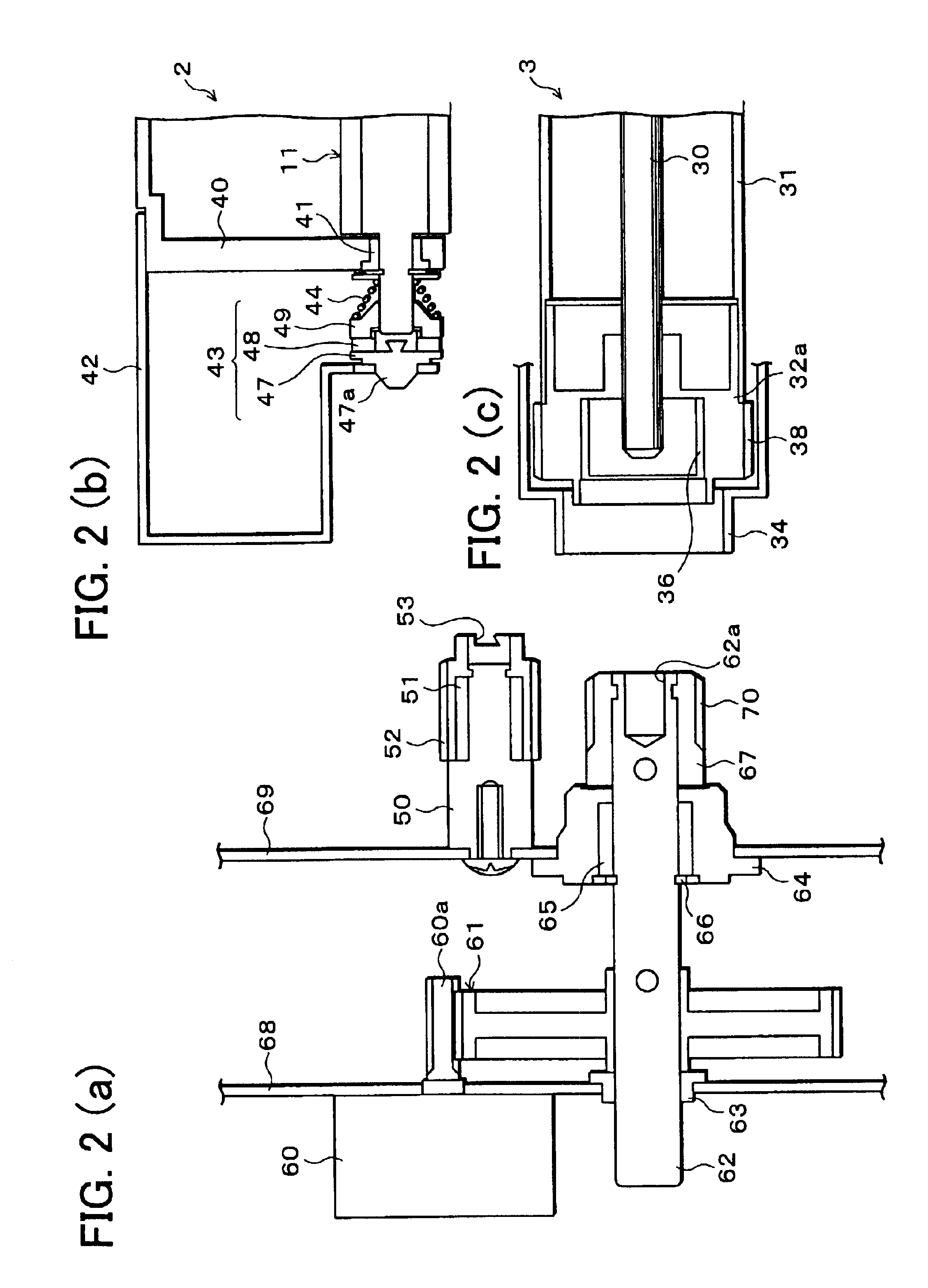
An image forming apparatus is provided with a photoreceptor drum which includes a cylindrical drum whose surface is coated with a photosensitive layer, and a rear-side drum flange section; and a developer. A coupling section at which the photoreceptor drum is attached to or detached from an image forming apparatus main body includes an input section and an apparatus output section. The input section is includes an internal gear having teeth of an involute curve formed in an inner surface of the rear-side flange section and receives rotation driving force from the image forming apparatus main body. The apparatus output section is composed of an external gear having teeth in the same shape and in the number as the internal gear, and outputs the rotation driving force from the image forming apparatus main body to the input section.

Description

FIELD OF THE INVENTION[0001]The present invention relates to an image forming apparatus of an electro-photographic system such as a copying machine, a printer, a facsimile etc., and also relates to a photoreceptor drum adopted in such image forming apparatus.BACKGROUND OF THE INVENTION[0002]Conventionally, in a copying machine, a printer, a facsimile, or other image forming apparatus of the electro-photographic printing system, a toner image is formed by developing an electrostatic latent image formed on an image holding member (photoreceptor), and further transferring the toner image formed onto a sheet to be affixed thereto, thereby forming an image on a sheet. For this image holding member, generally adopted is a photoreceptor drum whose peripheral surface is coated with a photosensitive film.[0003]By the way, in order to obtain a desirable image using the foregoing photoreceptor drum, it is required to exchange the photoreceptor drum periodically. In response, the photoreceptor ...

Claims


Application Information

Patent Timeline
Patent Type & Authority Patents(United States)
IPC IPC(8): G03G15/00F16C13/00G03G21/00F16D1/02
CPCG03G15/757
Inventor HARADA, YOSHIKAZUYAMANAKA, TOSHIOKIDO, EIICHIINO, TOSHIAKI
Owner SHARP KK
Learn More