
Full color holographic image combiner system

a holographic image and combiner technology, applied in the field of image generation, can solve the problems of reducing the perceived depth of the image, introducing image blurring, and requiring very expensive lens assemblies to form color corrected images, and achieve the effect of high resolution

Inactive Publication Date: 2005-06-14
MARSUPIAL HLDG
View PDF4 Cites 179 Cited by
  • Summary
  • Abstract
  • Description
  • Claims
  • Application Information

AI Technical Summary

Benefits of technology

[0030]It is an advantage of the present invention that the virtual image is high resolution and can be located at a distance from several inches to several miles from the equipment.
[0031]These and other objects, features, and advantages of the invention are accomplished by a heads up display comprising equipment for generating a virtual image in the field of view of an observer. The equipment includes a light source having a wavelength range less than 2 nm.

Problems solved by technology

Many existing systems use broadband light and require very expensive lens assemblies to form color corrected images.
Holographic systems are an inexpensive solution to the color correction problem, but they can introduce image blurring due to bandwidth generated problems.
Additionally, the bandwidth of the light source limits the perceived depth of the image, with a wide bandwidth light source requiring the image to be placed close to the observer to minimize image distortions and blur.
Such delays can constitute a significant safety issue, especially in situations where events occur very rapidly, e.g. in automobiles and aircraft, as well as in situations where the shear size and scale of the applications can put others at risk very quickly in spite of relatively slow moving equipment, e.g. equipment in construction zones and boats).
In addition, existing systems are expensive, often requiring lenses that cost thousands of dollars.
The bulk of existing systems and publications and patents were developed for low information content systems because the technology for high information content systems has not been sufficiently developed for field use.
The difference between high and low information content displays is significant because high information content displays require high resolution that is not feasible in low information content systems.
All the heads up displays are limited in resolution and the distance of the virtual image.

Method used


Image

  • Full color holographic image combiner system
  • Full color holographic image combiner system
  • Full color holographic image combiner system

Examples


Embodiment Construction

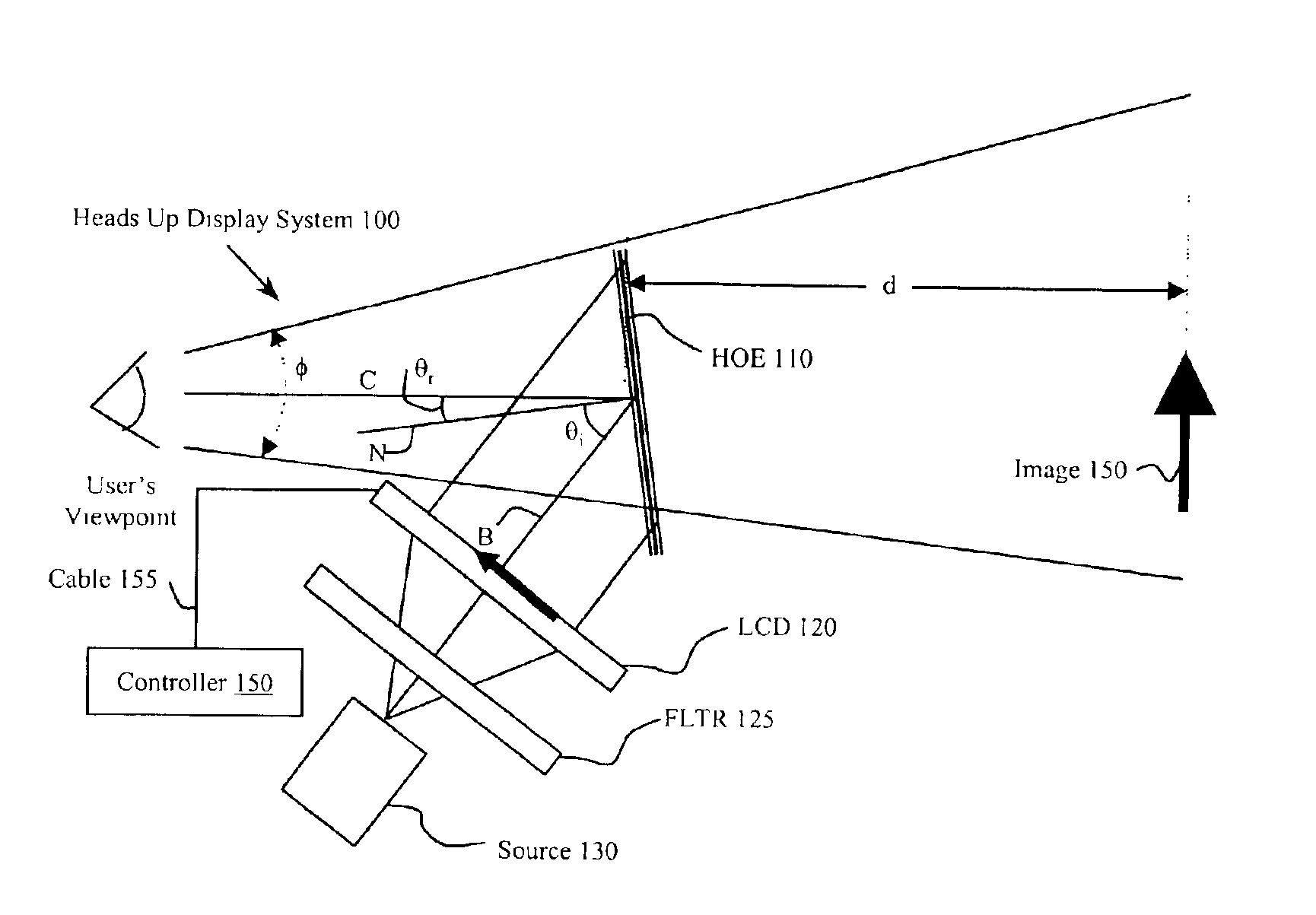
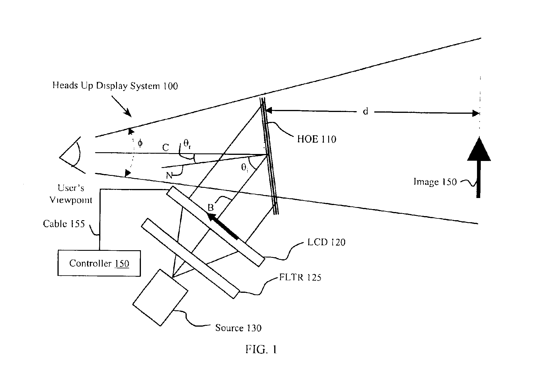
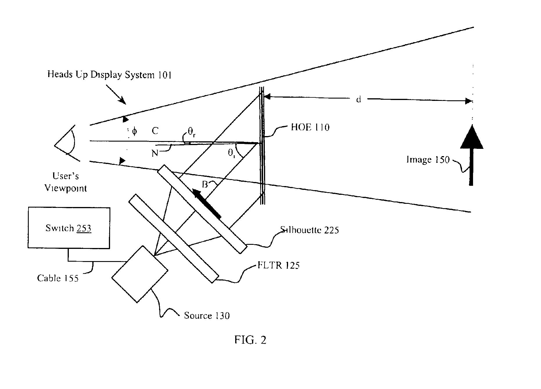
[0041]The present invention improves equipment for generating a virtual image in the field of view of an observer. The virtual image may be several inches to several miles from the equipment. Such equipment includes a light source that shines a pattern on a holographic optical element (HOE). The observer looks through the HOE and sees the virtual image of the pattern as well as real objects in the field of view. In the case of a VR or simulator, no real scenery is involved. The HOE can cover only a portion of the field of view to as much as the entire field of view. The HOE can also be located so as to cover none of the field of view. The present inventors found that by providing a very narrow range of wavelengths, less than 2 nm, the resolution of the virtual image is significantly improved. They also found several schemes for providing patterned light having such a narrow range of wavelengths. These schemes include providing a low-pressure gas discharge, a gas panel display, a las...


PUM


Abstract

A device, such as a heads up display, includes equipment for generating a virtual image in the field of view of an observer. The equipment includes at least one light source having a wavelength range less than 2 nm. The light source can be a low pressure gas discharge lamp. The device also includes a holographic optical element that provides a virtual image. The device also includes an image source, such as a mask or an LCD. In one embodiment the holographic optical element combines an image on a display with an ambient image. The holographic element provides multiple colors undistorted in a virtual image appearing to the observer as converging from the same distance.

Description

[0001]This application claims priority of provisional patent application No. 60 / 327,377, filed on Oct. 4, 2001.FIELD OF THE INVENTION[0002]This invention generally relates to image generation. More particularly, it relates to a display that provides an image that overlaps a field of view. Even more particularly, it relates to a heads up display (HUD) for providing information to a viewer overlapping a scene.BACKGROUND OF THE INVENTION[0003]Heads up displays (HUD's) have been well known for many years, and are used or are being considered for use in many applications including medical, scientific data visualization, aircraft, automobiles, boats, large farm equipment, and heavy-duty construction equipment. In a vehicular application, the driver can see the HUD in the field of view along with the road ahead and real objects on or near the road. Thus, using a HUD, an automobile driver can see the instrument panel superimposed on road without having to glance away to the display, focus o...

Claims


Application Information

Patent Timeline
IPC IPC(8): G02B27/01G02B5/32G02B27/00
CPCG02B5/32G02B27/0103G02B2027/012G02B2027/0118G02B2027/0112
Inventor PARKER, WILLIAMPARKER, JULIE
Owner MARSUPIAL HLDG
Learn More