Dynamically reconfigurable aperture coupled antenna
- Summary
- Abstract
- Description
- Claims
- Application Information
AI Technical Summary
Benefits of technology
Problems solved by technology
Method used
Image
Examples
Embodiment Construction
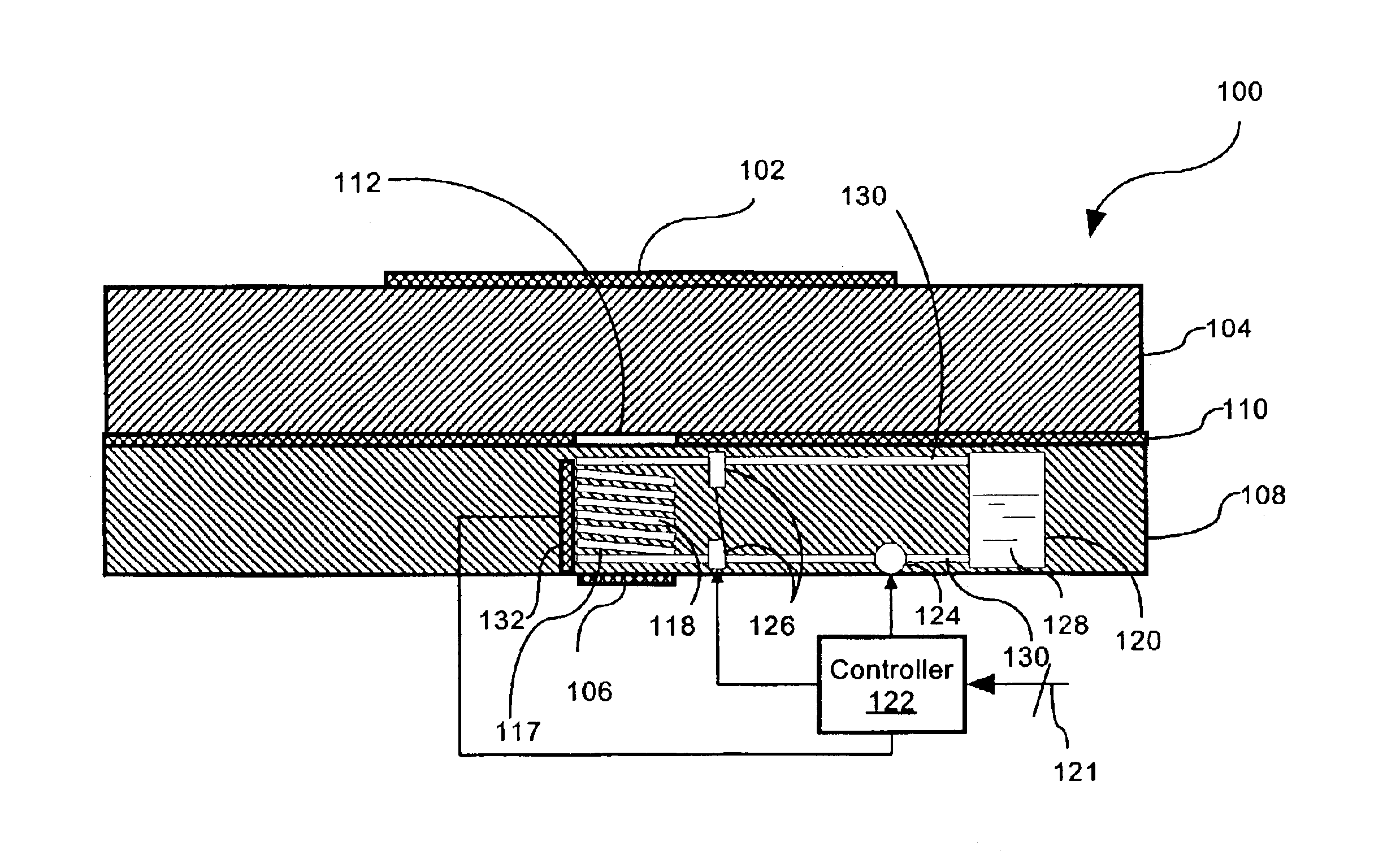
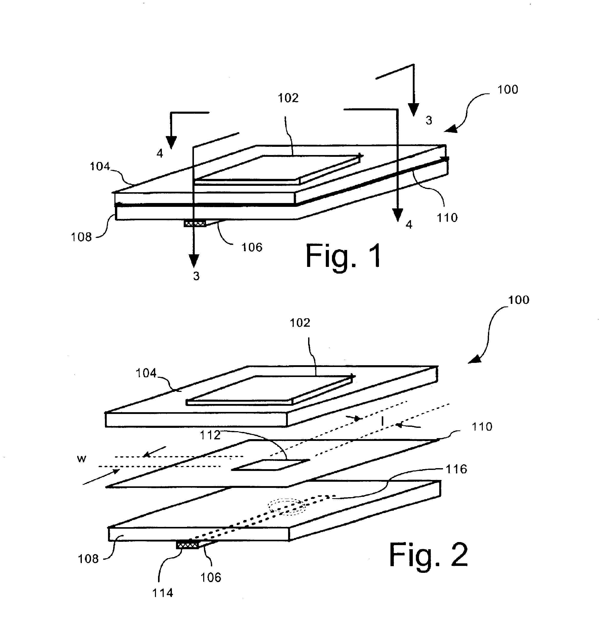
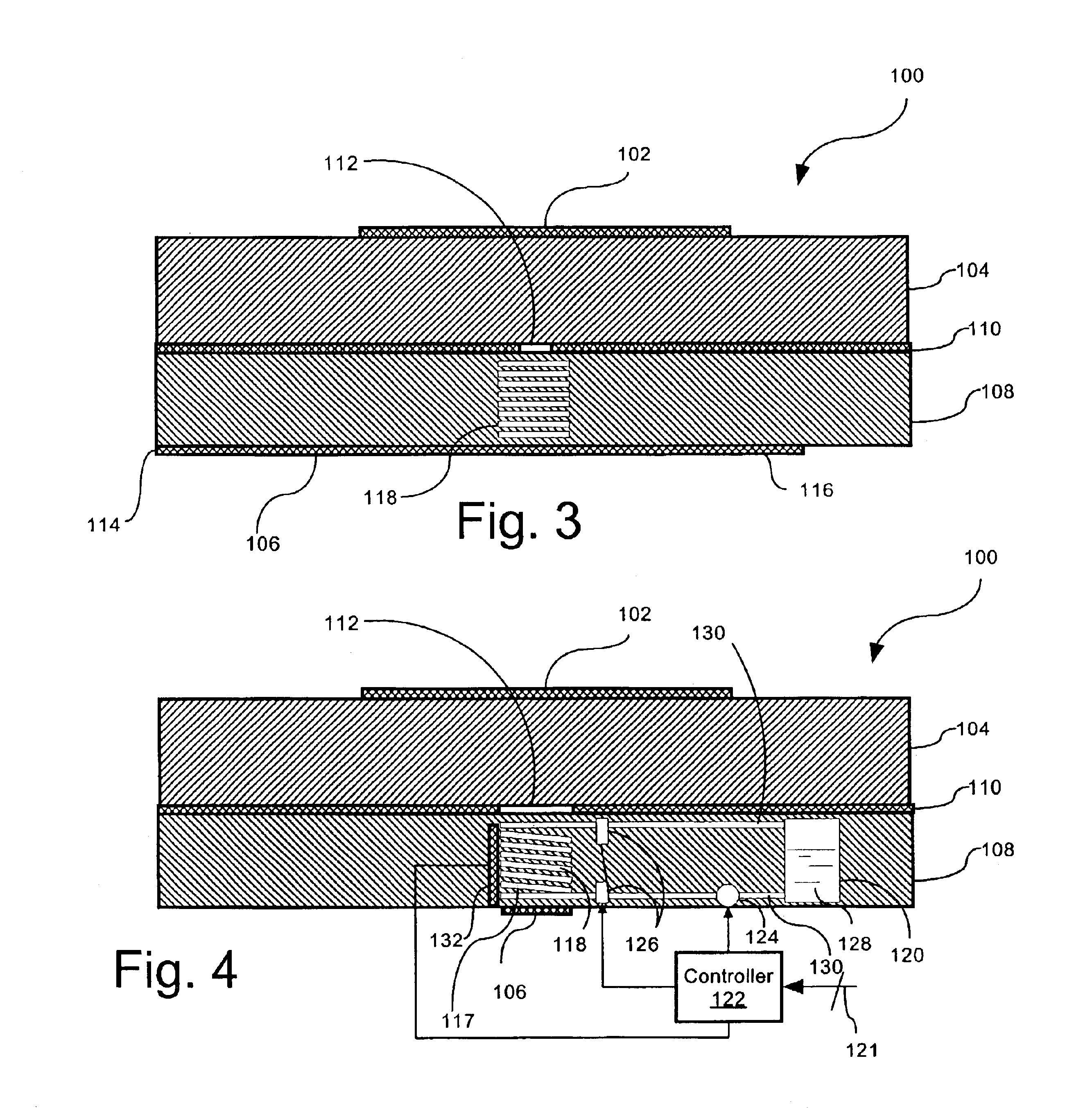
[0017]FIG. 1 is a perspective view of an aperture-fed patch antenna 100 that is useful for understanding the invention. The antenna is-comprised of a radiating element 102 disposed on a dielectric antenna substrate 104. The radiating element 102 in FIG. 1 is shown as having a square geometry as is common for patch type antennas, but it should be understood that the invention is not so limited. Instead, the radiating element 102 can have any of a wide variety of geometric designs as would be known to those skilled in the art.
[0018]A feed line 106 can be disposed on a surface of the antenna 100 opposed from the radiating element 102. According to a preferred embodiment, the feed line 106 can be a microstrip transmission line as shown. However, the invention is not limited in this regard and other arrangements are also possible. For example, feed line 106 could also be arranged in a buried microstrip or stripline configuration.
[0019]As illustrated in FIGS. 1 and 2, the feed line 106 ca...
PUM
 Abstract
Description
Claims
Application Information
 - R&D
- Intellectual Property
- Life Sciences
- Materials
- Tech Scout
- Unparalleled Data Quality
- Higher Quality Content
- 60% Fewer Hallucinations
Browse by: Latest US Patents, China's latest patents, Technical Efficacy Thesaurus, Application Domain, Technology Topic, Popular Technical Reports.
© 2025 PatSnap. All rights reserved.Legal|Privacy policy|Modern Slavery Act Transparency Statement|Sitemap|About US| Contact US: help@patsnap.com


