
Current rectifier assembly for rotating electrical machines, in particular motor vehicle alternators

a technology of current rectifier and alternator, which is applied in the direction of magnetic circuit rotating parts, magnetic circuit shape/form/construction, transportation and packaging, etc., can solve the problems of increasing cooling capacity and known rectifier arrangement incompatible with alternators of higher power, and achieve the effect of mitigate the drawback

Inactive Publication Date: 2005-06-14
VALEO EQUIP ELECTRIC MOTEUR
View PDF8 Cites 6 Cited by
  • Summary
  • Abstract
  • Description
  • Claims
  • Application Information

AI Technical Summary

Benefits of technology

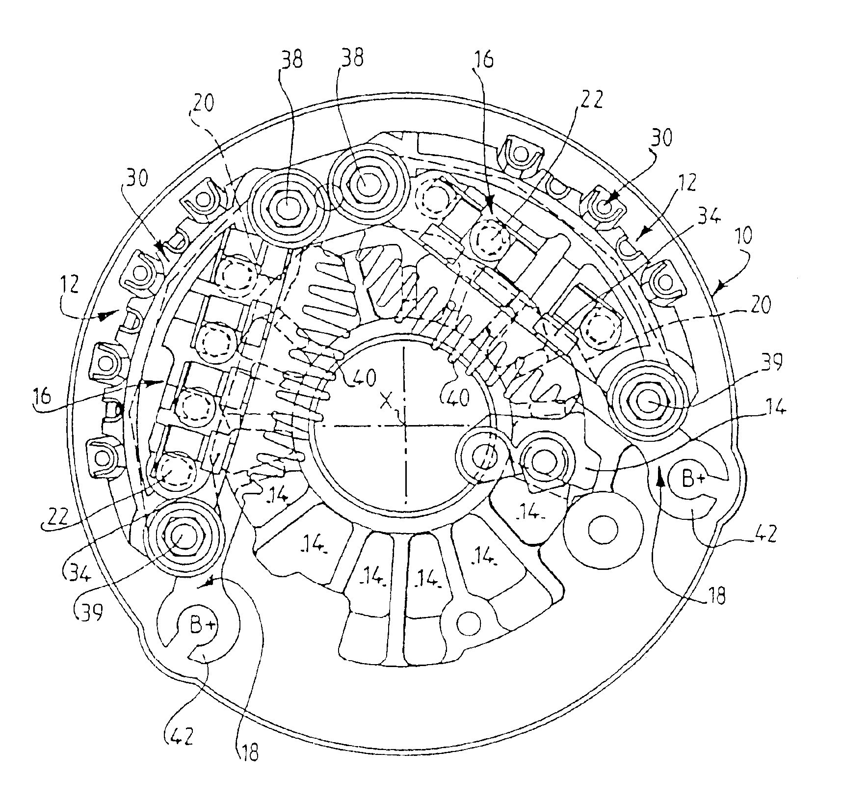
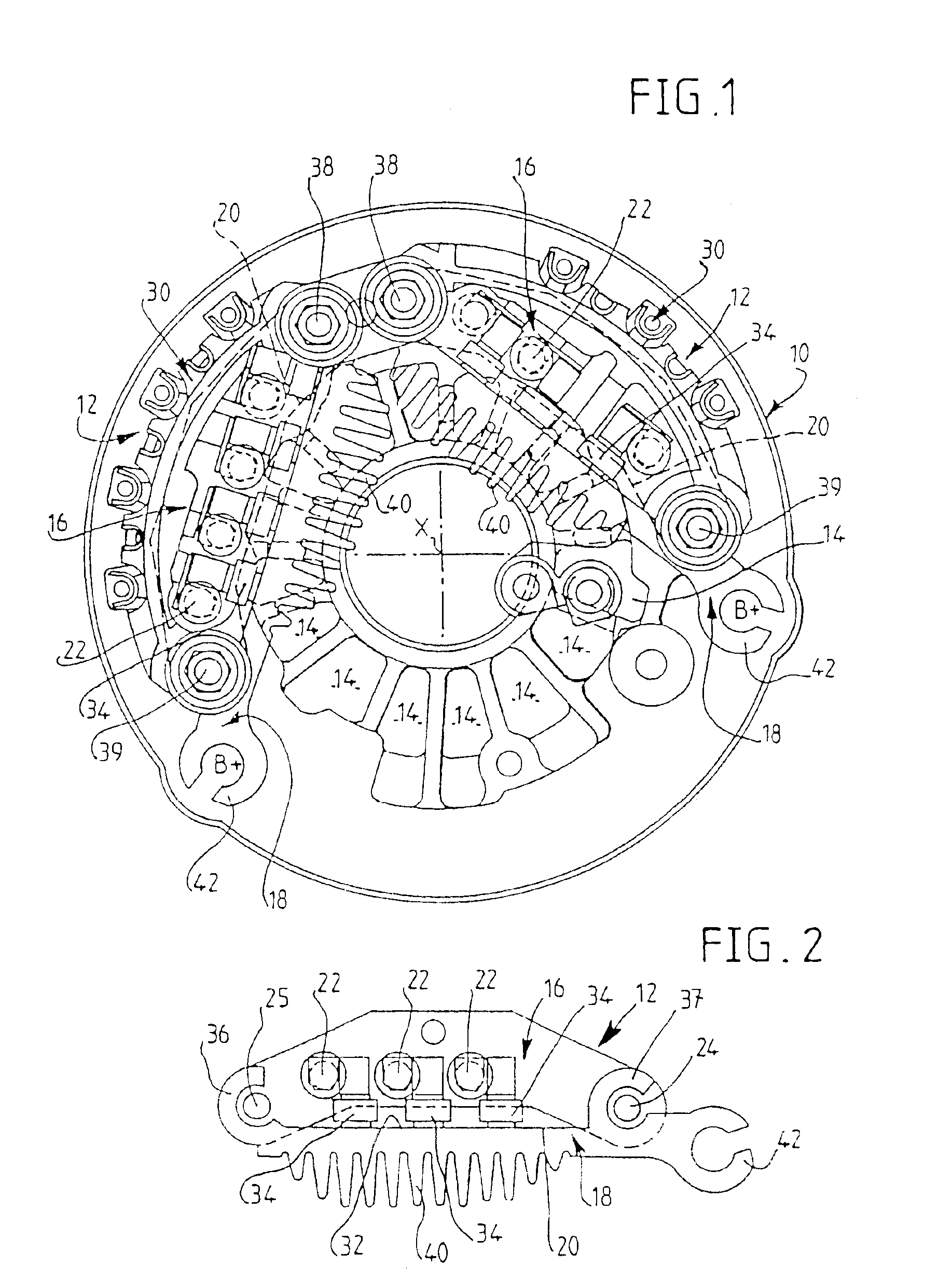
The present invention aims to improve the heat exchange of a rectifying arrangement by using a positive diode support device with increased heat exchange surface area. The support device can be fixed to the rear bearing by three fixings, including one in the joining area of two parts. The two support parts can be fixed by separate support plates that are joined together. The two support plates have fixing lugs that align with a passage hole for a fixing member. The fixing lugs have a reduced height compared with the height of the support plate. The arrangement can be produced in the form of a single molded piece or an arc of a circle. The orientation of the cooling fins towards the axis of the machine is chosen so that they extend radially in the middle area of the device. The radial length of the fins varies over the length of the parts for the supports for the positive diodes.

Problems solved by technology

The rectifying arrangement which has just been described briefly has the major drawback that it is bulky and that the principle of the configuration of the supports and of the arrangement of the diodes does not allow an increase in the cooling capacity, which makes this known rectifying arrangement incompatible with alternators of higher power.

Method used


Image

  • Current rectifier assembly for rotating electrical machines, in particular motor vehicle alternators
  • Current rectifier assembly for rotating electrical machines, in particular motor vehicle alternators
  • Current rectifier assembly for rotating electrical machines, in particular motor vehicle alternators

Examples


Embodiment Construction

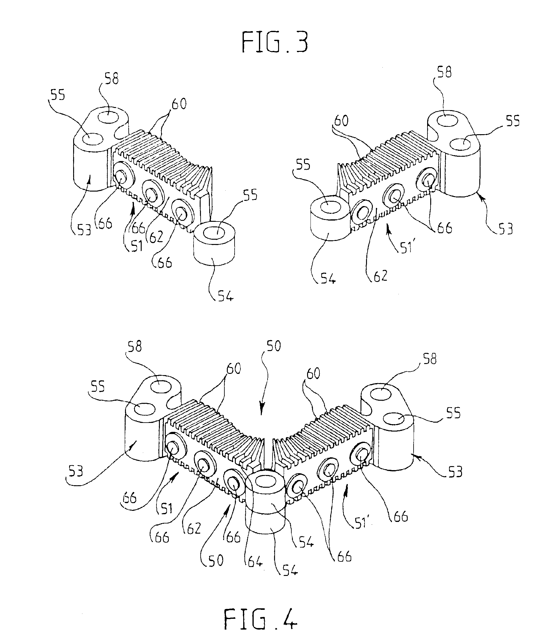
[0031]FIG. 4 illustrates a first embodiment of a positive radiator device according to the invention designated by the general reference 50, which is obtained by assembling two moulded positive radiators 51, 51′ with identical structures, shown in FIG. 3. Each radiator 51, 51′, with a straight elongate shape overall, has, at each of its ends, a lug 53, 54 for fixing to the rear bearing of the machine which has in it a hole 55 for the passage of a fixing member such as a screw or a tie rod with the interposing of an electrically insulating sleeve (not shown). The fixing lug 54 situated on the same side as the joining of the two radiators 51, 51′ has a cylindrical shape with a height corresponding, in the example depicted, to half the height of the body of the radiator. The fixing lug 53 situated at the opposite end of the radiator also comprises a passage hole for a fixing member 55 a hole 57 for receiving the B+ output terminal of the rectifier. Here the radiators are identical.

[003...


PUM


Abstract

The invention concerns a current-rectifying arrangement for rotary electrical machines of the type comprising a support (50, 51, 51′) for a plurality of positive diodes (66), a support for a plurality of negative diodes, forming part of the rear bearing of the machine, and a device for cooling by the creation of a forced axial flow of a cooling fluid through the rectifying arrangement, the support for the positive diodes carrying radial cooling fins (60) on its front face oriented towards the axis of the machine; the positive diode support device (66) being produced in the form of at least one moulded piece (50, 51, 51′), whose face oriented towards the aforementioned axis carries fine cooling fins (60).The invention can be used in alternators for motor vehicles.

Description

FIELD OF THE INVENTION[0001]The invention concerns a current-rectifying arrangement for rotary electrical machines, in particular alternators for motor vehicles, of the type comprising a support device for a plurality of positive diodes, having the general form of a plate of elongate shape, a support for a plurality of negative diodes in the form of a plate advantageously forming part of the rear bearing of the machine, a connector for the diodes and a device for cooling by creating a forced flow of a cooling fluid, such as air, in the axial direction of the machine, through the rectifying arrangement, the supports for the positive and negative diodes and the connector being superimposed in the direction of the axis of the machine and the positive diode support carrying cooling fins on its front face so as to form a radiator, which extend in the axial flow, in the radial direction of the machine. These supports are metallic, as is the rear bearing connected to earth. The rear bearin...

Claims


Application Information

Patent Timeline
Patent Type & Authority Patents(United States)
IPC IPC(8): H02K11/04H02K9/06H02K9/04B60R16/02H02K9/28
CPCH02K11/046H02K9/06H02K11/05H02K9/22H02K11/049
Inventor AESCHLIMANN, MICHELARRIGHI, SEBASTIENFAVEROLLE, PIERREHEVIA, THIERRYSCHULTE, DIRK
Owner VALEO EQUIP ELECTRIC MOTEUR
Learn More