
Radiator fastening system for hinge support

a technology of hinge support and radiator, which is applied in the field of radiators, can solve the problems of high installation cost, dust in the environment of radiators, and inability to remove radiators from the house,

Inactive Publication Date: 2015-07-28
I R C A S P A IND RESISTENZE CORAZZATE E AFFINI
View PDF20 Cites 0 Cited by
  • Summary
  • Abstract
  • Description
  • Claims
  • Application Information

AI Technical Summary

Benefits of technology

Facilitates easy installation and maintenance of radiators, improves air quality by reducing dust accumulation, and enhances heat exchange performance by maintaining the finning structure required for heat transfer.

Problems solved by technology

Removing radiators is not within everybody's reach due to the efforts required to unfasten them from the support brackets and due to the equipment required to disconnect the inflow and outflow manifolds of the vector fluid from the distribution installation.
Hence, the air breathed in an environment in which the radiators are full of dust, is unhealthy.
Installing traditional radiators is costly due to the same aforementioned problems, because it requires the intervention of two operators to install a radiator due to the precision required in nearing the radiator to the support brackets and due to the fact that while one of the two operators holds the radiator, the other one bolts it to the brackets.
Therefore, the technical problem is that of solving the difficulty in installing a radiator and subsequently removing the dusts which accumulate thereon over time.

Method used


Image

  • Radiator fastening system for hinge support
  • Radiator fastening system for hinge support
  • Radiator fastening system for hinge support

Examples


second embodiment

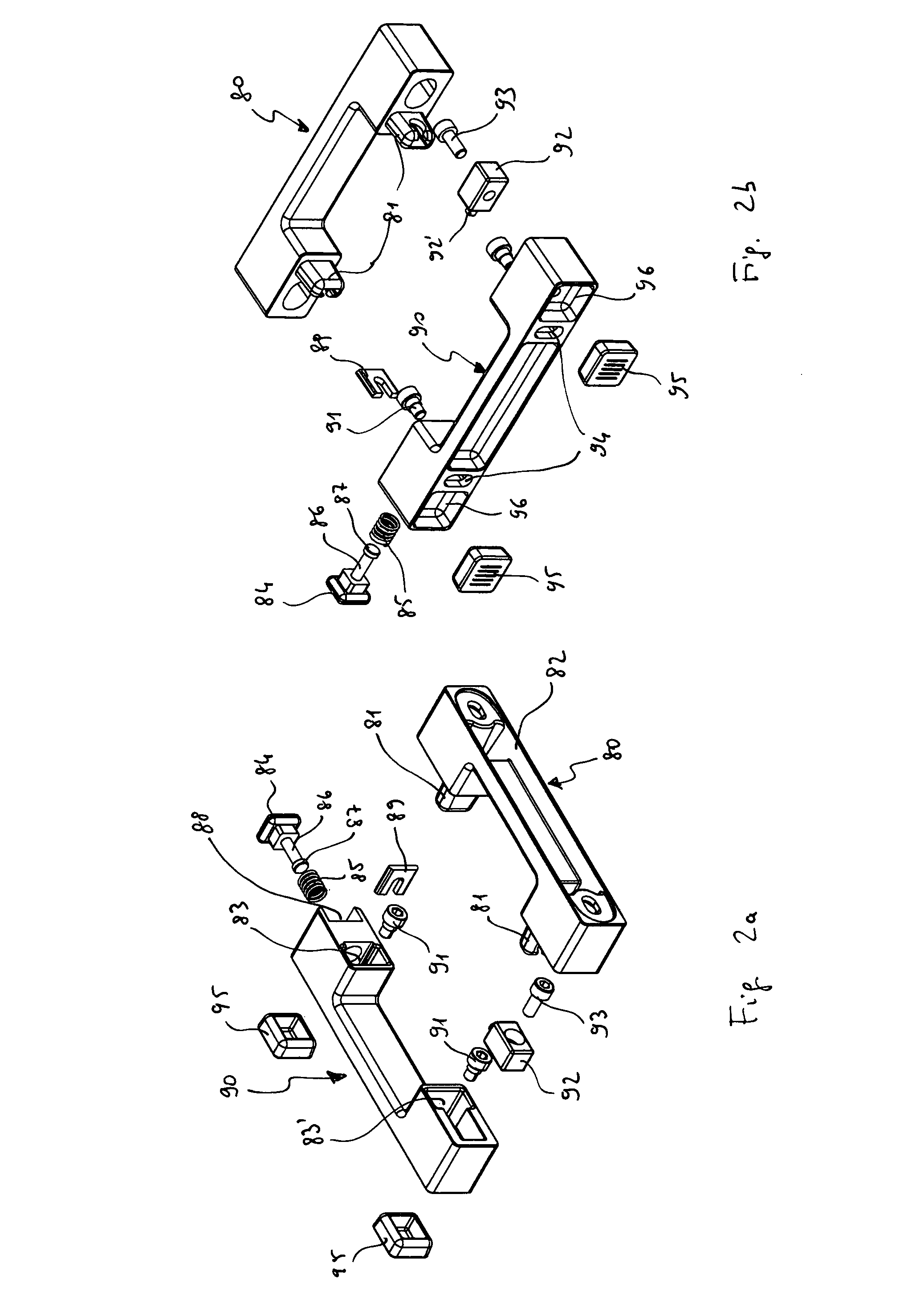
[0071]This second embodiment of the upper support 2 comprises a first part 80 to be fixed to the support wall of the radiator, comprising a fixing bracket 82 provided with two pins or protrusions 81, and a second part 90 integrally fixed to the radiator and suitable for being engaged with said first part 80 of the upper support 2, comprising two seats 83, 83′ for accommodating the respective pins 81.

[0072]The second part 90 of the upper support 2 is advantageously provided with a normally closed button 84 with return spring 85 which permits unfastening of said second part 90, by means of pressure on the button itself, and thus unfastening of radiator 3 from the first part 80, and thus from the support wall.

[0073]The button 84 comprises a cylindrical pivot 86 provided at its terminal end with a cylindrical portion 87 of a greater diameter than the pivot 86 itself. The return spring 85 is accommodated on said pivot 86. The button 84 is accommodated in a seat 88 obtained in the second ...

first embodiment

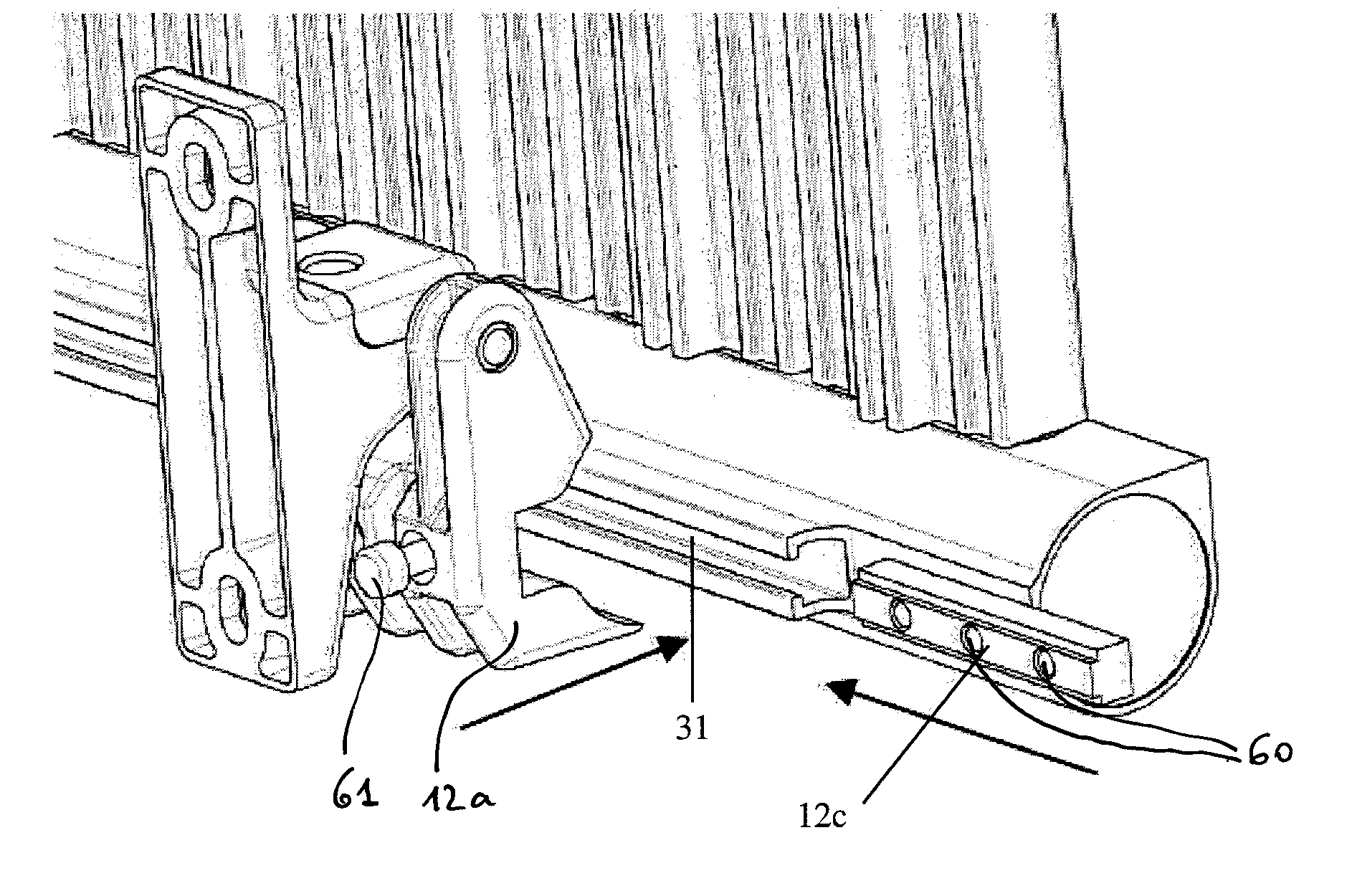
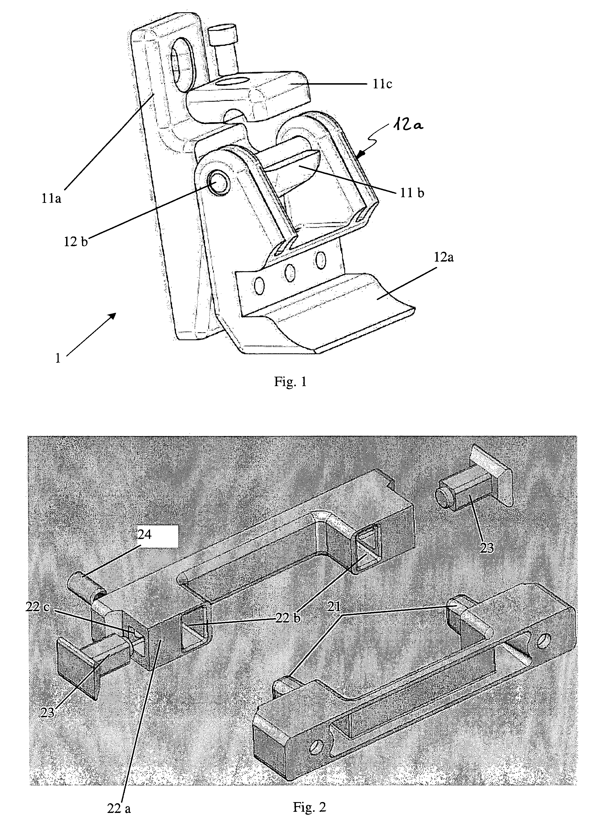
[0085]In the first embodiment, a snap pin 24 is provided to fix the counterpin 23 (FIG. 2). The radiator dimensions being precisely known, the second fixing brackets 22a, 82 may be wall-mounted before or after the first fixing brackets 11a are mounted.

[0086]Once the radiator is neared to the protrusions 11b, the radiator is blocked at the top by means of the upper support 2 and then the completion elements 11c are assembled.

[0087]The fixing brackets 11a, 22a and 82 may comprise holes or in any event means which allow the same to be wall-mounted.

[0088]Fixing the radiator to the wall may be preferably achieved by blocking means 2 comprising snap blocking elements (not illustrated) which advantageously permit to compensate for the mounting tolerances.

[0089]According to another aspect of the present invention, a radiator may integrally comprise both one or more pivots 12b and one or more pins 21, 81.

[0090]In particular, a preferred embodiment of a tilting radiator comprises an upper tub...


PUM


Abstract

A wall-mounted radiator comprising a support (1) adapted to make it tilting with respect to a support wall and possibly comprising blocking means (2) of the radiator to maintain it in a proximal or distal position with respect to said support wall. The support may be adapted to be associated with the radiator (3) so as to allow to adjust the fastening point so as to facilitate the installation thereof. Moreover, the support (1) may comprise a removable part (11c) in order to further simplify the installation of the radiator.

Description

FIELD OF THE INVENTION[0001]The present invention relates to a radiator with related fastening system, in particular a wall-mounted radiator.BACKGROUND ART[0002]Wall-mounted radiators are generally installed during the building step or when upgrading an environment and are not likely removed unless for their maintenance or for painting the walls on which they are installed.[0003]Generally, these radiators have a vertical development and may comprise several modules associated in relation to the needs.[0004]Two or more support brackets generally protrude from the wall, to which a radiator is bolted.[0005]Removing radiators is not within everybody's reach due to the efforts required to unfasten them from the support brackets and due to the equipment required to disconnect the inflow and outflow manifolds of the vector fluid from the distribution installation.[0006]For this reason, dusts and mites which are difficult to be removed accumulate on the rear surfaces of the radiators, i.e. ...

Claims


Application Information

Patent Timeline
Patent Type & Authority Patents(United States)
IPC IPC(8): F28F9/00F28F1/20A47K10/06F24D19/02F28F1/22F28D21/00F28F7/00
CPCF28F1/20A47K10/06F24D19/02F24D19/0209F24D19/0283F24D19/0293F28F1/22F24D2220/2054F28D2021/0035F28D2021/0036
Inventor VISENTIN, SIMONEARGENTON, MARCOPRAVATO, MICHELEPETERLE, MICHELE
Owner I R C A S P A IND RESISTENZE CORAZZATE E AFFINI
Learn More