Brake caliper thrust device, brake caliper and manufacturing method

a technology of brake calipers and thrust devices, which is applied in the direction of brake cooling, brake systems, transportation and packaging, etc., can solve the problems of deteriorating mechanical resistance performance, increasing the stroke of the brake pedal, and increasing the stroke of the piston

Active Publication Date: 2020-09-17
FRENI BREMBO SPA
View PDF0 Cites 1 Cited by
  • Summary
  • Abstract
  • Description
  • Claims
  • Application Information

AI Technical Summary

Benefits of technology

[0031]By virtue of the proposed solutions, an increase of the heat exchange surface of the brake caliper, accessible from the air surrounding the disc brake, may be obtained, without, thereby, weakening the caliper body.
[0032]By virtue of the proposed solutions, an improvement of the performance may be obtained, since the working temperature of the brake caliper decreases with respect to the working temperatures of the known brake calipers.
[0033]By virtue of the proposed solutions, an improvement may be obtained of the ventilation of the thrust devices of the brake caliper which contextually increases the thermal resistance of the thrust devices with respect to the known solutions, limiting the overheating thereof when in operating conditions.

Problems solved by technology

This deformation of the caliper body leads to an increase in the stroke of the pistons and therefore to an increase in the stroke of the brake pedal.
Therefore, the simultaneous increase in the temperature of the caliper body and the deformation thereof constitute the risk that the caliper body, when strongly overheated, deteriorates the mechanical resistance performance thereof.
The increase in the temperature of the pad and of the caliper body may affect the area in which the thrust devices, the cylinder-piston units, are provided, affecting the features of the brake fluid present in the intake ducts and in the cylinder chambers.
In extreme cases, the brake fluid itself may be brought to a boiling, thus forming in the intake ducts or in the chamber formed between the cylinder and the piston a gaseous state which is dangerously compressible and no longer adapted to readily and promptly transfer the braking command to the pistons and, therefore, to the pads.
Even more significant is the fact that, due to the overheating of the pad and of the caliper body, the elastic sealing and / or roll-back gaskets, provided at the interface between the piston and the cylinder, are likely to undergo a thermal stress which they are not adapted to bear, being usually made of rubber or plastic and therefore unadapted to withstand high operating temperatures, thus plastically deforming and causing a premature deterioration of the braking performance.
However, these known solutions are extremely complex to realize, assemble and maintain, especially in everyday vehicles, although being highly or very highly performing.
In fact, when the heat has unfortunately accumulated in the mass of the caliper body, the cooling times thereof, in known caliper embodiments, are very long, thus exposing the braking system, in the case of repeated braking actions of considerable magnitude, to an even greater accumulation of heat and to an increased risk of the brake fluid boiling as well as to a deterioration of the resistance performance of the caliper body construction material.

Method used


Image

  • Brake caliper thrust device, brake caliper and manufacturing method
  • Brake caliper thrust device, brake caliper and manufacturing method
  • Brake caliper thrust device, brake caliper and manufacturing method

Examples


Embodiment Construction

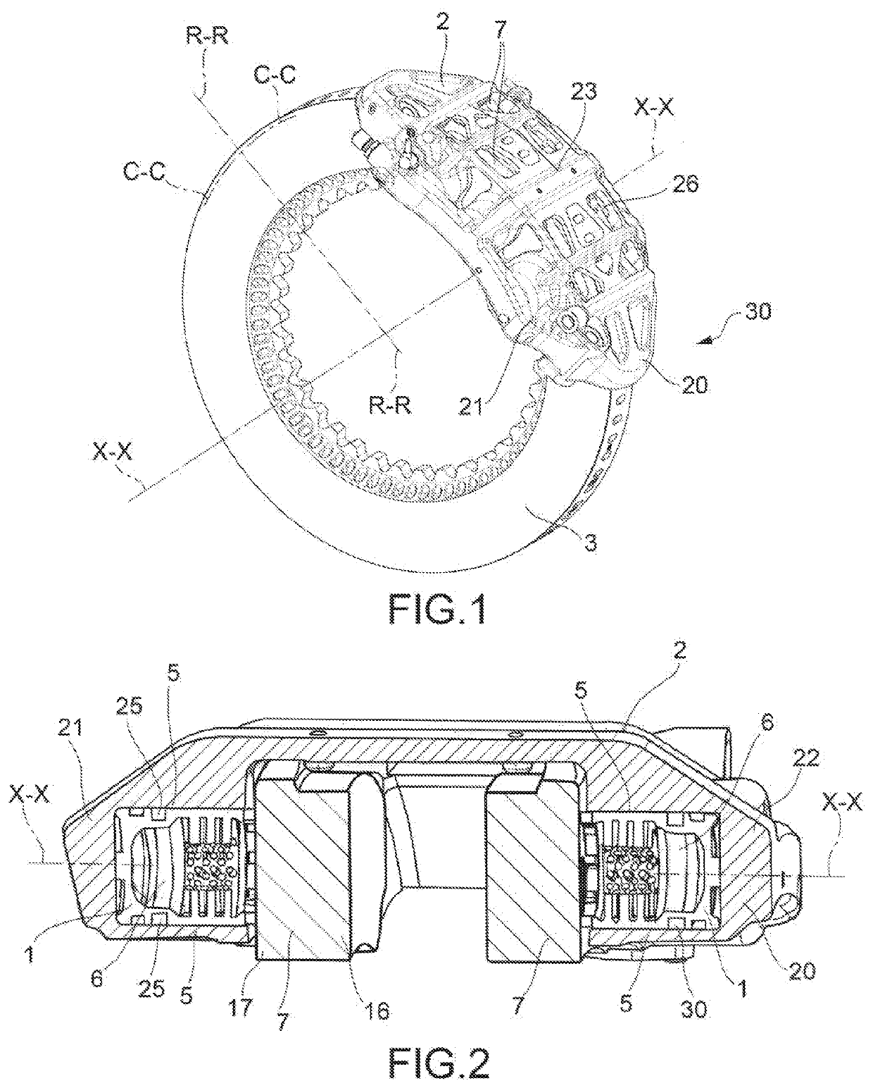
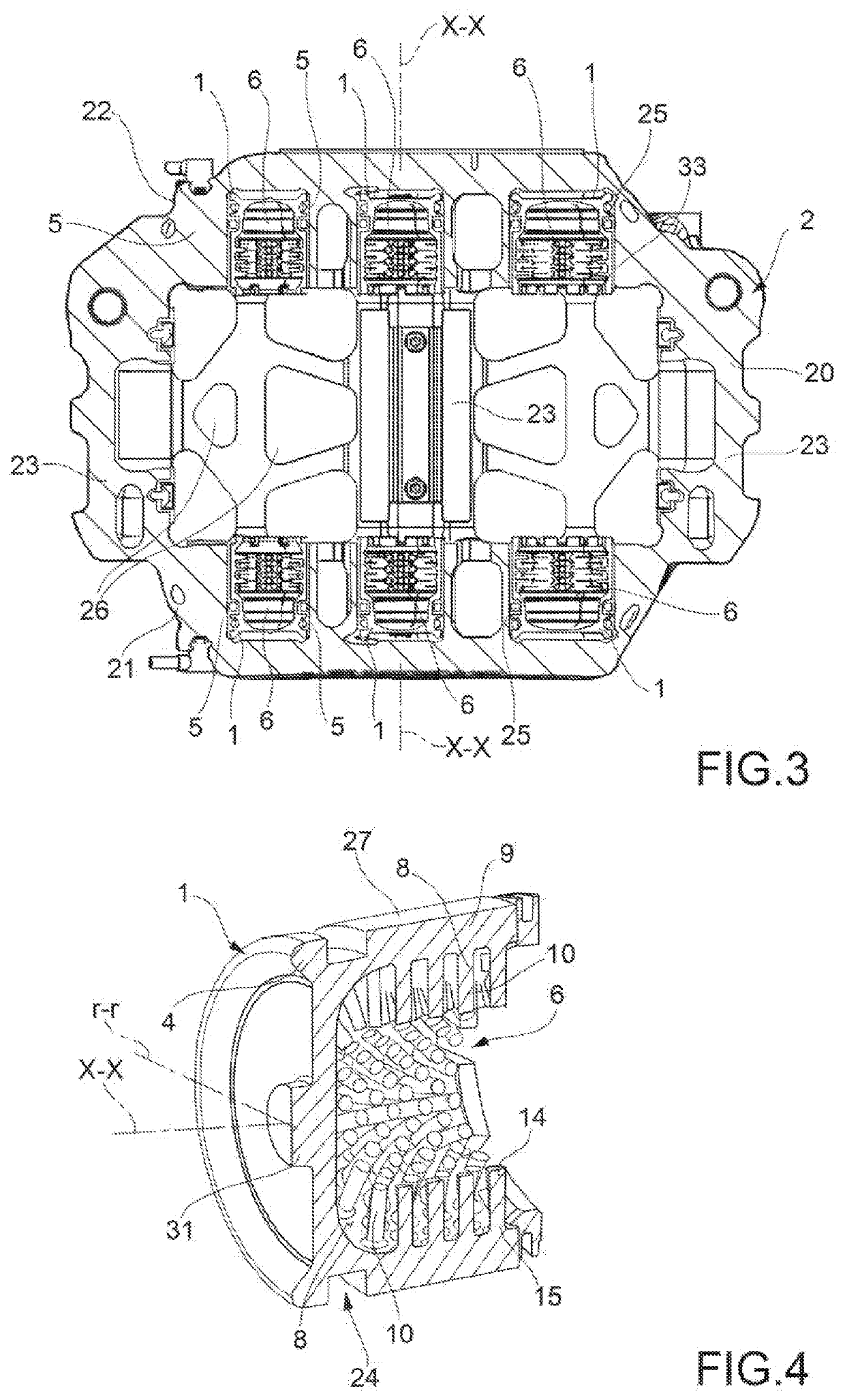
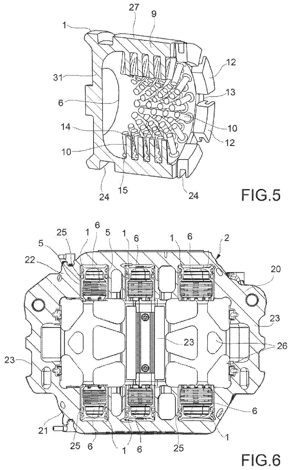
[0045]In accordance with a general embodiment, a brake caliper thrust device 1 for a disc brake 30 comprises a thrust device body 4, adapted to be translated inside a guide device 5.

[0046]Said disc brake 30 defines an axial direction X-X coincident with or parallel to the axis of rotation of a brake disc 3 of the disc brake 30, a radial direction R-R, substantially orthogonal to said axial direction X-X, and a tangential or circumferential direction C-C, orthogonal both to said axial direction X-X, and to said radial direction R-R. The axial direction X-X is meant to be defined also on a thrust device 1 when considered alone. Said thrust device further defines a thrust device radial direction r-r, orthogonal to said axial direction X-X and incident thereto. Preferably, said guide device 5 is adapted to guide the translation of said thrust device body 4 along the axial direction X-X when in operating conditions.

[0047]Said thrust device body 4 defines an internal cavity 6 at least par...


PUM


Abstract

A brake caliper thrust device for a disc brake is provided. The brake caliper thrust device has a thrust device body adapted to be translated inside a guide device, the thrust device body defining an internal cavity at least partially open and facing towards an object to be pushed, including a brake pad associable with the thrust device. The internal cavity is delimited by at least one internal surface defined by at least one wall of the thrust device. From the at least one wall of the thrust device, at least one heat dissipation element protrudes into the internal cavity, adapted to increase the extension of the at least one internal surface to evacuate heat accumulated by the at least one wall of the thrust device.

Description

FIELD OF THE INVENTION[0001]It is the object of the present invention a brake caliper thrust device for a disc brake.[0002]The present invention also relates to a brake caliper comprising said thrust device.[0003]Furthermore, the present invention relates to a disc brake.[0004]The present invention further relates to a manufacturing method of a brake caliper thrust device.BACKGROUND ART[0005]In a disc brake, the brake caliper is generally arranged straddling the external peripheral margin of a brake disc, adapted to rotate about an axis of rotation defining an axial direction (X-X). Furthermore, in a disc brake, a radial direction (R-R), substantially orthogonal to said axial direction (X-X) is defined, as well as a tangential or circumferential direction (C-C), orthogonal both to said axial direction (X-X), and to said radial direction (R-R).[0006]The brake caliper usually comprises a caliper body having two elongated portions arranged so as to face opposite braking surfaces of a b...

Claims


Application Information

Patent Timeline
Patent Type & Authority Applications(United States)
IPC IPC(8): F16D65/847B60T5/00
CPCB60T5/00F16D2125/06F16D2065/789F16D65/847F16D65/78
Inventor ARIENTI, ROBERTOCOMENDULI, ALBERTOPENATI, DANIELE ANGELOODONI, ANDREA
Owner FRENI BREMBO SPA
Why Eureka
Try Eureka