
Slide feeder with air bearing conveyor

a conveyor and slide technology, applied in the field of microscopy, can solve the problems of high cost, limited performance, and complex and relatively cumbersome mechanisms, and achieve the effect of reducing the number of slides to be fed to the microscope, and reducing the number of slides to be fed

Active Publication Date: 2005-06-14
DMETRIX INC
View PDF10 Cites 60 Cited by
  • Summary
  • Abstract
  • Description
  • Claims
  • Application Information

AI Technical Summary

Benefits of technology

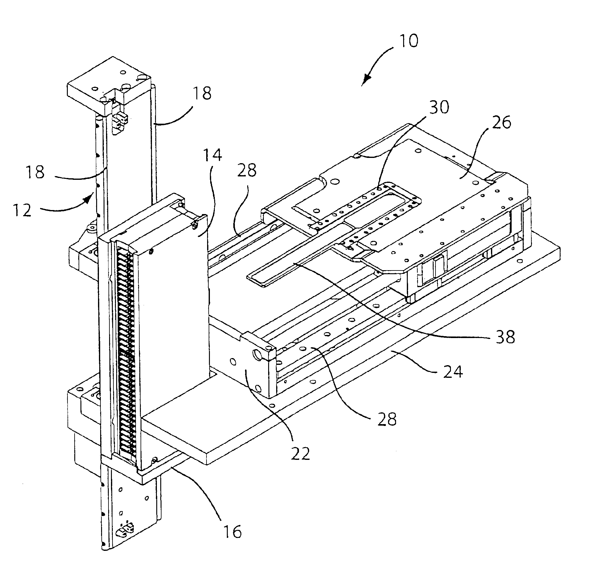
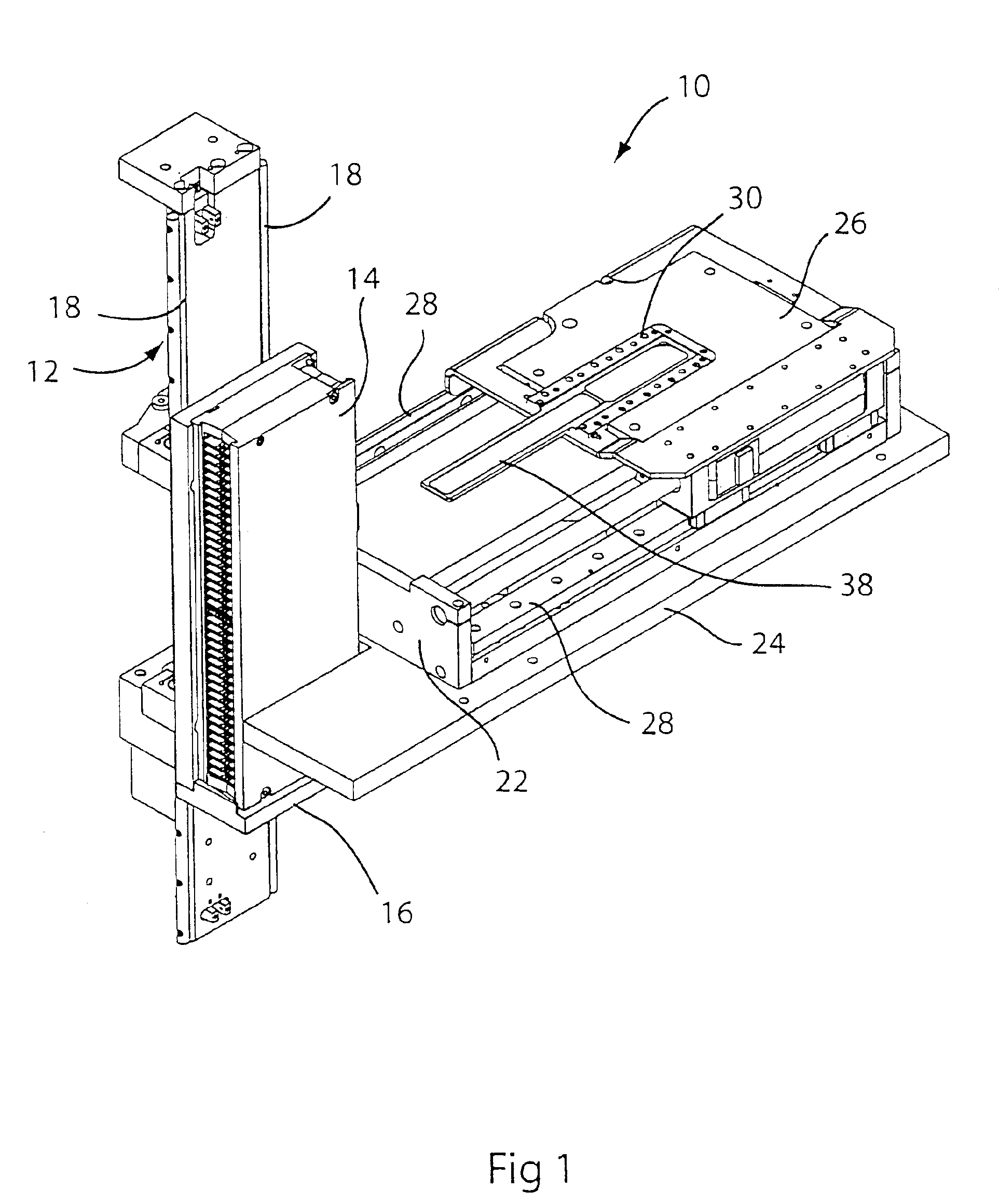
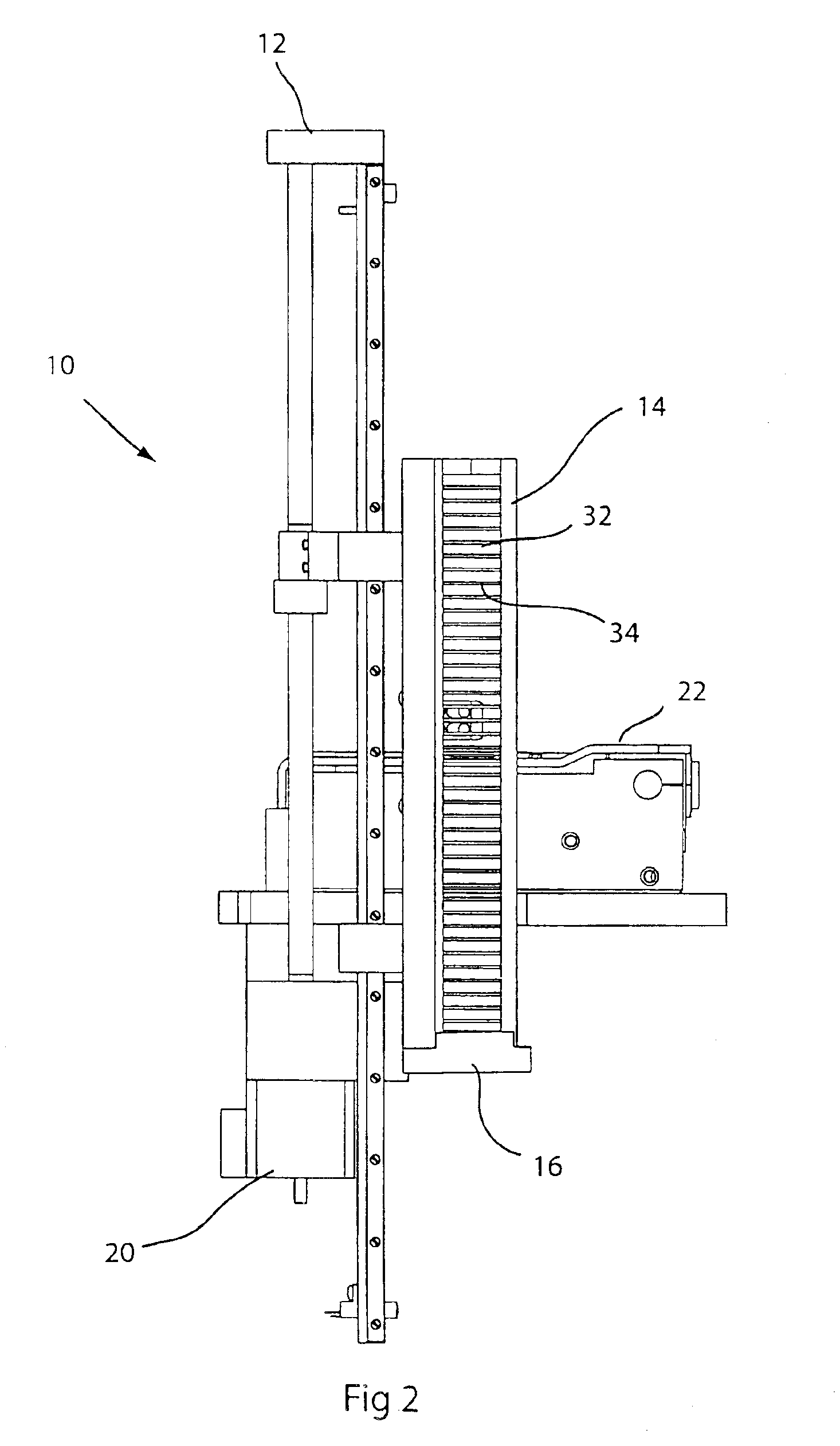
[0010]According to another aspect of the invention, the stage of the microscope is provided with a carriage adapted to move horizontally along a direct path between the stage and the slide magazine. A slide conveyor coupled to the carriage includes a tongue that is positioned in the magazine slot under the slide of interest when the carriage is at one end of its travel path, so that the tongue may be used to pick up the slide for translation to the stage of the microscope. When the carriage is moved over the stage in optical alignment with the microscope at the opposite end of its travel path, the tongue is completely removed from the magazine, so that the magazine may be freely moved vertically by the elevator to align another slide for retrieval and processing.

Problems solved by technology

While this recent robotic improvement of conventional “pick and place” technology has accelerated the ability to process slides, its performance is limited by the fact that each tray must be removed from a stack prior to retrieval of the slide of interest.
Very sophisticated and relatively cumbersome mechanisms are required to perform such multi-step functions, which is expensive to implement and limits the ability to achieve even greater throughputs.

Method used


Image

  • Slide feeder with air bearing conveyor
  • Slide feeder with air bearing conveyor
  • Slide feeder with air bearing conveyor

Examples


Embodiment Construction

[0024]The invention was motivated by the fact that the conventional pick-and-place robotic approach to automation is necessarily limited in its effectiveness by the speed and complexity of its mechanisms. Accordingly, the heart of the invention lies in the idea of utilizing air flow both to pick the slides from a storage magazine and to place them over a microscope stage in position for processing. This approach affords grater simplicity of design and operation and, correspondingly, produces materially greater throughputs.

[0025]As used herein, the term “plenum” refers to an enclosed space wherein the pressure is greater than the outside atmosphere. The term “runway” is used to designate a substantially horizontal strip along which a slide is moved by air jets, back-and-forth and end-to-end, between a storage position and a processing position, or between different storage or processing positions. A runway may be linear or curved and it may include a transfer structure, such as a tur...


PUM


Abstract

A slide loading mechanism utilizes compressed air as the transport medium to move the slides from a magazine to the stage of a microscope. The stage is provided with a carriage moving horizontally along a direct path between the stage and the magazine. A conveyor coupled to the carriage includes a tongue suitable for positioning under the slide of interest in the magazine when the carriage is at one end of its travel path, so that the slide may be picked up for translation to the stage of the microscope. When the carriage is moved to the opposite end of its travel path, the tongue is completely removed from the magazine, which may be freely moved vertically by an elevator to align another slide for processing. Directional air flow is used to suspend and transport the slide back and forth between the two ends of the conveyor

Description

BACKGROUND OF THE INVENTION[0001]1. Field of the Invention[0002]This invention is related in general to the field of microscopy. In particular, it relates to automated mechanisms to feed slides to a microscope from a removable slide magazine.[0003]2. Description of the Related Art[0004]In pathology and other biomedical practices, a sample is removed from a patient and fixed to a glass slide for staining and microscopic examination. For example, the morphology of the sample is analyzed to provide a qualitative assessment of its condition and to identify the presence of pathologic changes, such as may indicate progression towards a malignancy. For many decades, this visual procedure has been the diagnostic mainstay of pathology.[0005]With the advent of computers and sophisticated digital imaging equipment, researchers have extended the realm of these analytical procedures through the use of mechanized instrumentation for diagnostic and quantitative investigation. In such mechanized pr...

Claims


Application Information

Patent Timeline
IPC IPC(8): B65G1/00G01N35/00G01N35/04G02B21/34
CPCG01N35/00029G02B21/34G01N2035/00039G01N2035/0479G01N2035/00089
Inventor RUSSUM, WILLIAM C.
Owner DMETRIX INC
Learn More