
Signal type identification

a technology of type identification and signal, applied in the field of radio frequency signal measurement, can solve problems such as interference signals and lack of skill and experience necessary to discrimina

Inactive Publication Date: 2005-06-07
TEKTRONIX INC
View PDF20 Cites 131 Cited by
  • Summary
  • Abstract
  • Description
  • Claims
  • Application Information

AI Technical Summary

Benefits of technology

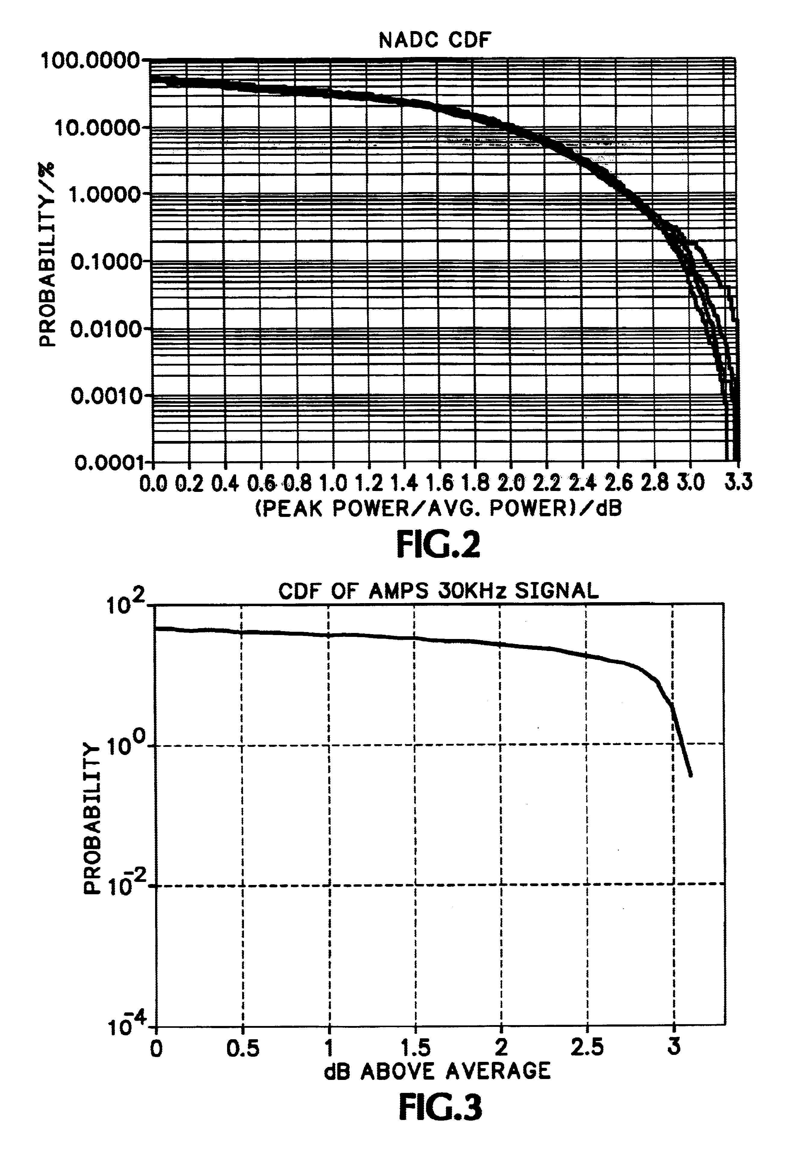
[0004]Accordingly the present invention provides a method of modulation identification for an unknown modulated signal. A frequency spectrum is displayed in a conventional manner and an operator selects an unknown signal so displayed in a conventional manner, such as touching the screen, adjusting a cursor, clicking a mouse cursor and the like. The selection activates an identification algorithm which processes the data representing the signal according to specified parameters. Typical parameters may be frequency, occupied bandwidth (OBW) and complementary cumulative distribution fu

Problems solved by technology

In measuring and testing RF systems there occur from time to time interfering signals.
In normal field testing and measuring conditions the operator may not be a skilled operator, technician or engineer and, thus, may not have the skill and experience necessary to discriminate and identify to which of the signal categories a particular unknown signal belongs.

Method used


Image

  • Signal type identification
  • Signal type identification
  • Signal type identification

Examples


Embodiment Construction

[0011]From the list of signals that need to be identified, it is seen that almost every signal type has some specific “signature” parameter. One such parameter may be the frequency. A database or table of stored information containing spectral band assignments for various types of modulated signals may be used. When a signal is selected by suitable means, such as cursor positioning via mouse or dial, touching or the like, the database may be consulted to see what signal or signals may be expected to exist at the selected frequency of the selected signal.

[0012]Another parameter is the “Occupied BandWidth of the signal” (OBW). Since the OBW measurement may be done directly on an intermediate frequency (IF) signal without demodulating the signal, it is fairly straight forward using existing algorithms, such as using fast Fourier transform (FFT) and estimating the number of bins for 95% of total power. Table 1 below shows signals that may be measured, the signals that have high correlat...


PUM


Abstract

A method of identifying a signal type uses parameters of the signal as a basis for automatic identification. A signal of interest is selected from a display of a spectral waveform for a specified frequency. An occupied bandwidth for the signal of interest is estimated and, if the occupied bandwidth is common to more than one known signal type, a complementary cumulative distribution function of peak power for the signal of interest is estimated. The signal type may be identified as a function of these parameters. Additionally the frequency of the signal of interest may be compared with a database of spectral assignments for known signal types to provide further information about the signal of interest.

Description

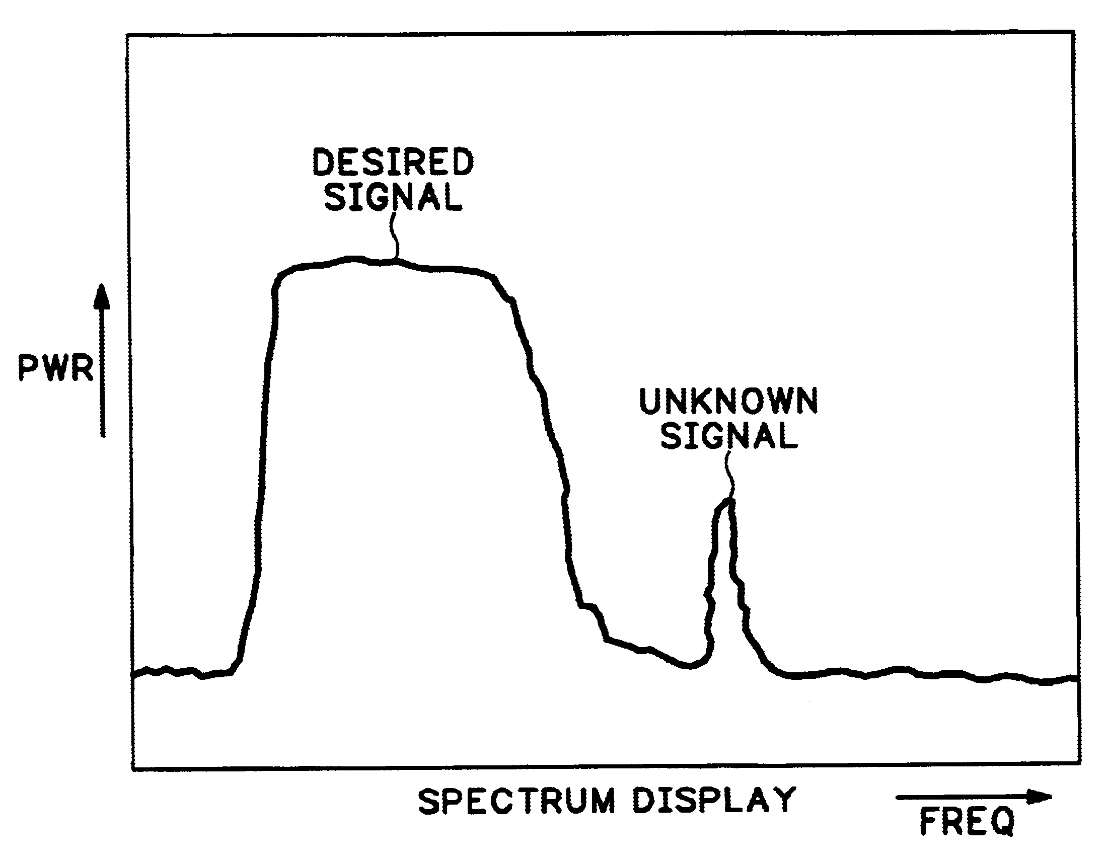
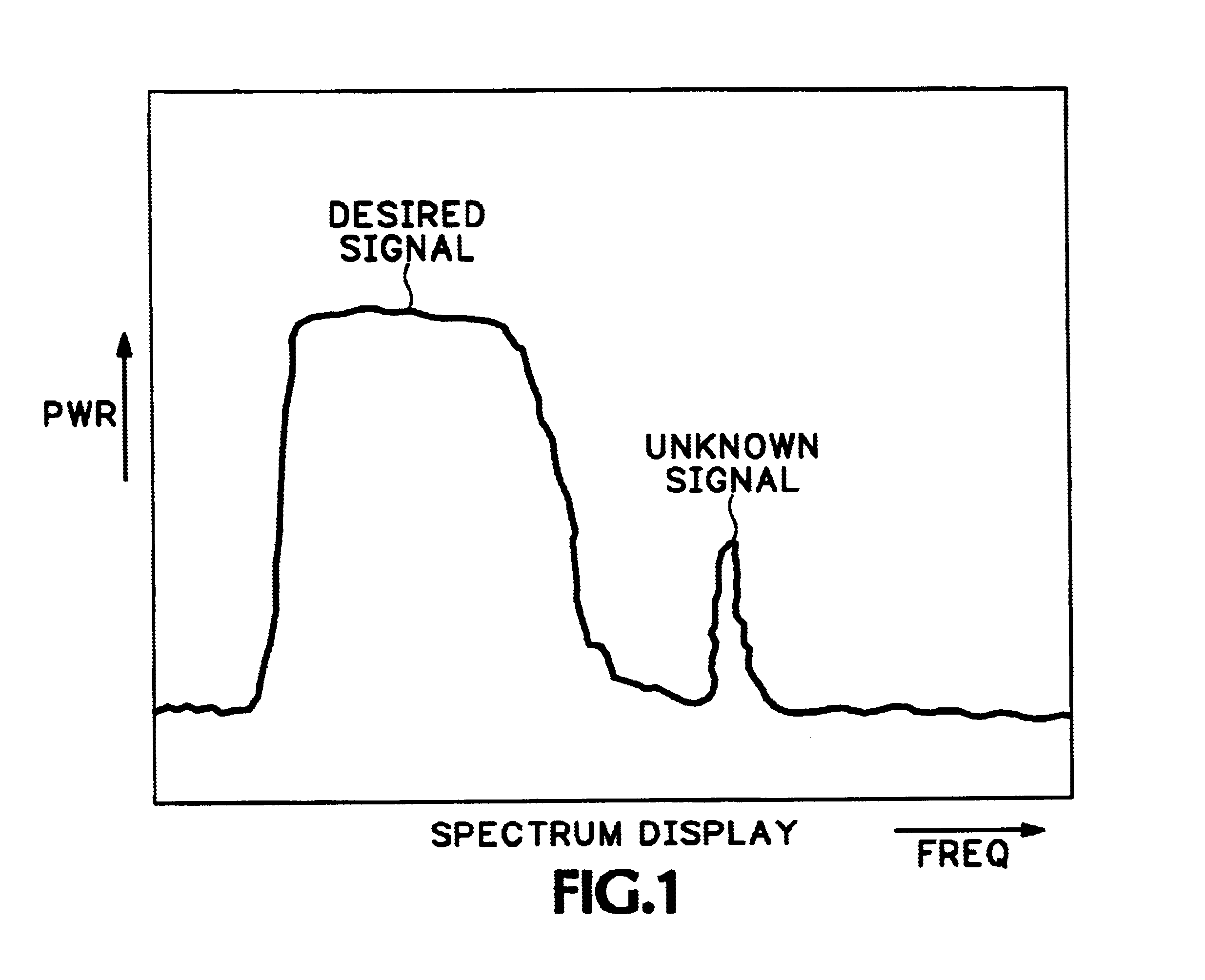
BACKGROUND OF THE INVENTION[0001]The present invention relates to radio frequency (RF) signal measurements, and more particularly to the signal type identification of an unknown signal.[0002]In measuring and testing RF systems there occur from time to time interfering signals. This may show up on a spectral display, such as that generated by a spectrum analyzer, as an extraneous signal in the frequency domain, as shown in FIG. 1. A skilled operator, technician or engineer may manually identify the interfering signal by making appropriate adjustments to the spectrum analyzer control parameters and having skill in identifying those parameters that are unique to different types of signals, both modulated and unmodulated. There are many signal types that may occur in the normal environment, such as IS-95 CDMA signals, North American Digital Cellular (NADC) TDMA signals, Global System for Mobile (GSM) TDMA signals, Analog Mobile Phone System (AMPS) FM signals, Continuous Wave (CW) signal...

Claims


Application Information

Patent Timeline
IPC IPC(8): H04L27/00G01R23/16G01R31/00H04B17/00
CPCH04L27/0012
Inventor DESHPANDE, NIKHILHILL, THOMAS C.JENKINS, R. EBENENGHOLM, KATHRYN A.
Owner TEKTRONIX INC
Learn More