
Structure around a speaker unit and applied electric or electronic apparatus thereof

Inactive Publication Date: 2005-06-07
SHIMA SYST
View PDF24 Cites 29 Cited by
  • Summary
  • Abstract
  • Description
  • Claims
  • Application Information

AI Technical Summary

Benefits of technology

[0055]This enables to determine material for a structure around a speaker unit, the size, formation, and shape of the structure more freely. A novel design therefore can be produced without being swayed by the formation and shape of a conventional speaker system. As a result, a speaker system of higher quality can be provided easily.
[0110]As a result, electric and electronic apparatus for which importance has not been attached to tone quality can also use a miniature, lightweight, and low-cost speaker which can reproduce clear sounds.

Problems solved by technology

However, such a sealed box does not always achieve theoretically perfect high fidelity sounds so as to be recognized as a standard type as a structure around a speaker unit, because the sound absorbing material 31 could not absorb all the sound waves and slight harmful interference waves remain, and the damper effect due to the closed air within the sealed box restricts a free vibration of the cone paper.
If the enclosure member itself vibrates unnecessarily, then a harsh noise will be produced.
As a result, a strange sound is produced.
If members etc. of the headphones used in the second listening method vibrate unnecessarily, a harsh noise will be produced.
Without a device, it will be difficult for the other types of speaker store produce the original sound with high fidelity and to reproduce heavy low-pitched sounds with presence.
However, many people dislike them because of their uncomfortableness or obstacle cords.
Therefore, even when a speaker unit and an ear are a short distance away, sound which comes from the speaker unit will be very faint.
As a result, L-channel sound waves interfere with R-channel sound waves via the lightweight enclosure.
That is to say, even if a stereo is used, the listener cannot enjoy its stereophonic effect.

Method used


Image

  • Structure around a speaker unit and applied electric or electronic apparatus thereof
  • Structure around a speaker unit and applied electric or electronic apparatus thereof
  • Structure around a speaker unit and applied electric or electronic apparatus thereof

Examples


first embodiment

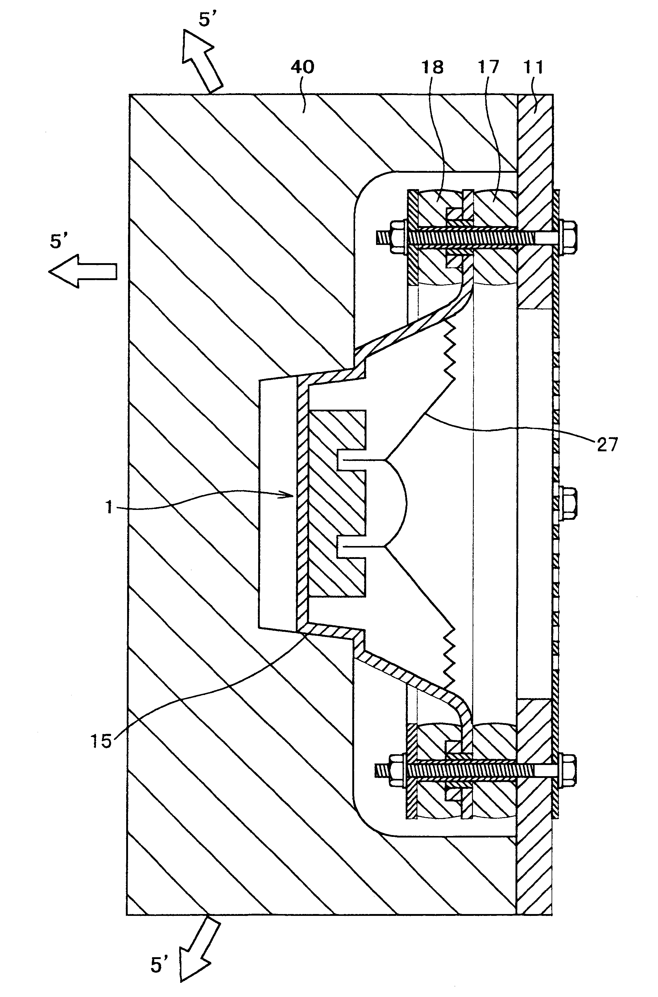
[0269]FIG. 13 shows the present invention by way of design drawing, in which FIG. 13A is a front view, FIG. 13B is a sectional view taken along the line A—A of FIG. 13A, and FIG. 13C is an exploded sectional view thereof. A punching board, decorative wire mesh, top grille (protection net with a frame) 88 or the like may have a function to keep the profile as well as protecting the cone paper 27.

[0270]Instead of the baffle board, the back sound screening board 51a made of a mat with a hole portion, which mainly consists of a bag sealing therein gel, is employed. FIG. 13 shows only one speaker unit 13, however, a plurality of units may be used for obtaining a stereo effect. Because the Curllock member 40a has a fiber structure with sufficient air permeability and elasticity and with proper rigidity, it can retain the compact speaker unit 1 to a certain position. The rear cover 89 may be made from the same material as that introduced with reference to FIG. 13C, and is made of a punchin...

second embodiment

[0271]FIG. 14 shows the present invention by way of design drawing, in which FIG. 14A shows a front view and a vertical sectional view taken along the line B—B, and FIG. 14B is a transverse sectional view taken along the line C—C of FIG. 14A. The Curllock member 40b has substantially trapezoidal section, and its front projection is covered, from the front part, with the back sound screening board 51b made by a mat with a hole portion mainly consisting gel.

[0272]Since it is obvious to one skilled in the art, a punching board, decorative wire mesh, top grille 88a or the like is omitted from FIG. 14A. The same can be said to FIGS. 15 and 16.

[0273]Herein, the back sound screening board 51b surrounds the front part of the speaker unit (as a sound source) with a trough-shaped curved surface, and the front and rear of the speaker unit 1 is effectively and separately shut out. Therefore, the object of the present invention can be achieved by an area smaller than the back sound screening boa...

third embodiment

[0274]FIG. 15 shows the present invention by way of design drawing, in which FIG. 15A is a front view, and FIG. 15B is a sectional view taken along the line D—D of FIG. 15A.

[0275]The Curllock member 40c has substantially trapezoidal section, and the center portion of its top surface is provided with a conical hole for the insertion of the speaker unit 1.

[0276]Herein, the back sound screening board 51c has a trapezoidal shape, and the bottom surface thereof is provided with a circular hole so as to surround the speaker unit 1 from the front part.

[0277]Therefore, the front and rear of the speaker unit 1 is effectively and separately shut out by the back sound screening board 51c. Therefore, the object of the present invention can be achieved by an area smaller than the back sound screening board 51a formed by a flat plate, and pure and clear sound can be obtained by a small and compact structure.


PUM


Abstract

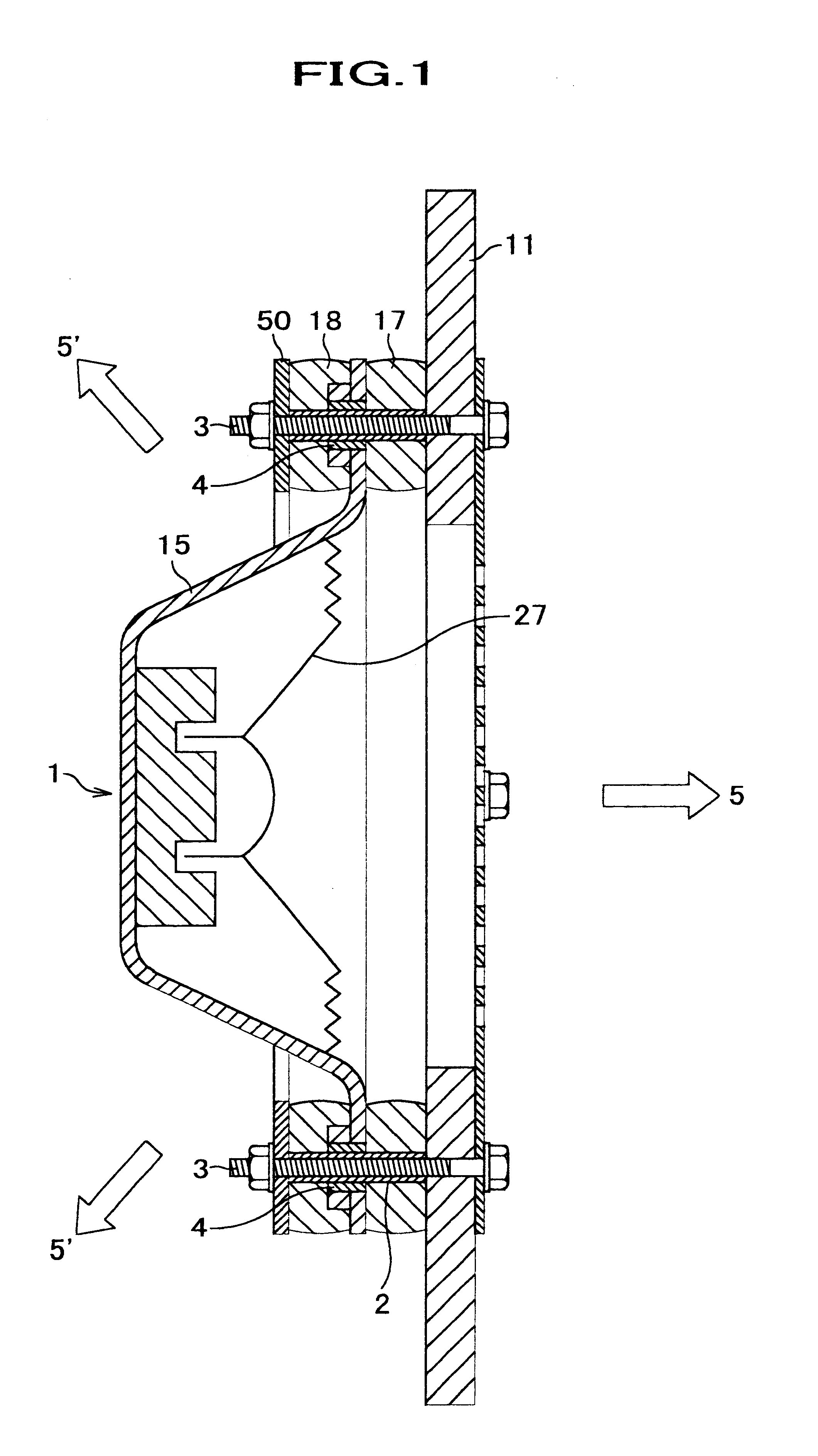
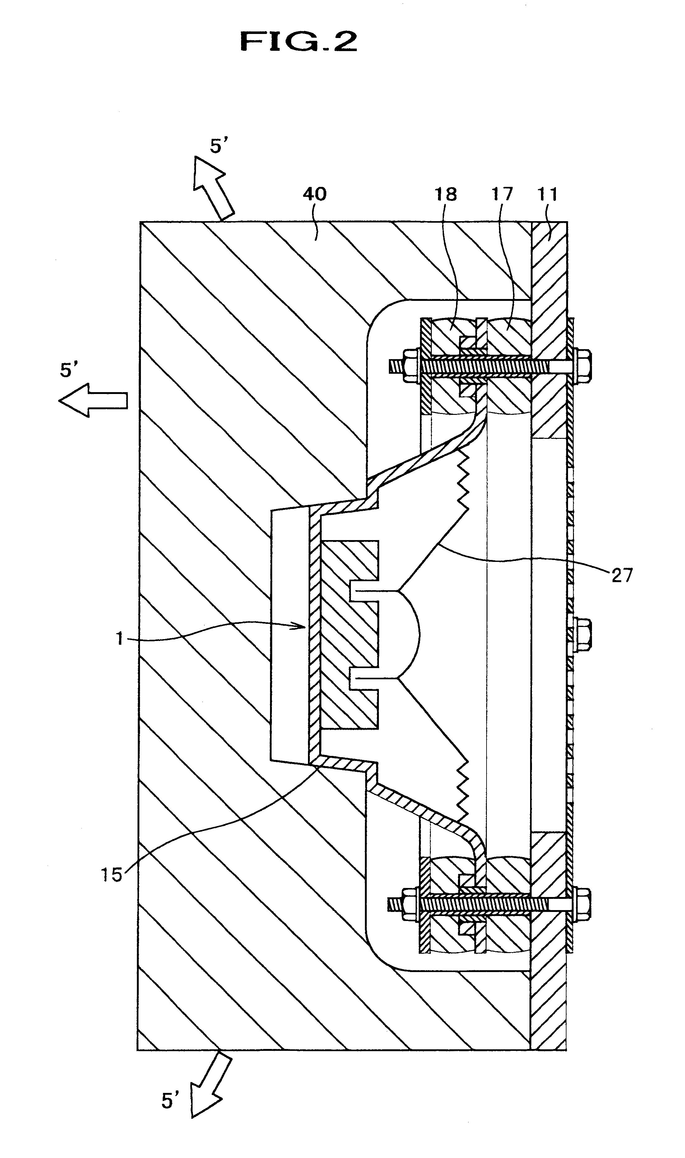
A compact lightweight speaker system without a resonance box that can reproduce the original sound with high fidelity. A speaker unit is located on a baffle board with a vibration absorbing member between a frame of the speaker unit and the baffle board. Furthermore, an acoustic resonance reflecting board of a vertical flat board type based on the operating principle of a passive radiator is formed by the baffle board and a flat board being similar to the baffle board. As a result, a compact smart design will be produced. It is applicable to an electric or electronic apparatus which produces sound.

Description

FIELD OF THE INVENTION[0001]The present invention relates to a compact, lightweight, and simple speaker system and / or a structure around a speaker that enables to reproduce sounds, including heavy low-pitched sounds, with high fidelity.[0002]The present invention is also applicable to a minicomponent stereo, television, telephone, radio cassette recorder, built-in speaker for personal computer, 5.1 channel speaker, or the like.[0003]Furthermore, the present invention is applicable to a speaker used inside a pillow or inside the pillow portion of an easy chair etc.[0004]Moreover, the present invention is applicable to a back sound screening board that is located near a speaker to improve sound effects.BACKGROUND OF THE INVENTION[0005]Acoustic apparatus called speakers usually transmit sound by converting electrical sound signals output from an amplifier or the like to sound vibrations by the use of electromagnetic or electrostatic stress, transmitting the sound vibrations to a vibrat...

Claims


Application Information

Patent Timeline
IPC IPC(8): H04R1/02
CPCH04R1/025H04R1/2834H04R5/023
Inventor SHIMA, YOSHIHARU
Owner SHIMA SYST
Learn More