
Heater system for diesel engines having a selective catalytic reduction system

Inactive Publication Date: 2005-06-07
DETROIT DIESEL
View PDF9 Cites 30 Cited by
  • Summary
  • Abstract
  • Description
  • Claims
  • Application Information

AI Technical Summary

Benefits of technology

[0010]In accordance with one aspect of the invention, an automotive diesel engine includes an engine block with a coolant system and a selective catalytic reduction system operably connected to the exhaust system for reducing air pollutant emissions. The catalytic reduction system includes a urea tank for storing and delivering urea solution to the exhaust system. A first heater element is mounted in the coolant system and a second heater element is mounted in the urea tank that preferably stores an aqueous solution of approximately 32.5% urea. It is desirable that the first heating element is mounted in the water jacket of the coolant system.

Problems solved by technology

One of the hurdles in using such an aqueous urea solution is that it is subject to freezing.
Besides running with elevated emissions, an engine may run afoul of certain regulations without the liquid urea.
While these solutions are acceptable during operation of the diesel engine when the coolant is heated by the engine and the battery is being recharged by the alternator, they are not adequate for long storage or overnight shut down of the diesel engine in cold weather.
Such a remedy is expensive requiring an extra tank, and relies on the premise that the amount of starting urea solution is sufficient while the main tank is warmed and thawed.
This premise may not be justified during extreme cold weather starts which can result in a phase of engine operation when there is no thawed or liquid reductant available.
It is also well known that diesel engines are harder to start than regular gasoline engines in cold weather.

Method used


Image

  • Heater system for diesel engines having a selective catalytic reduction system
  • Heater system for diesel engines having a selective catalytic reduction system

Examples


Embodiment Construction

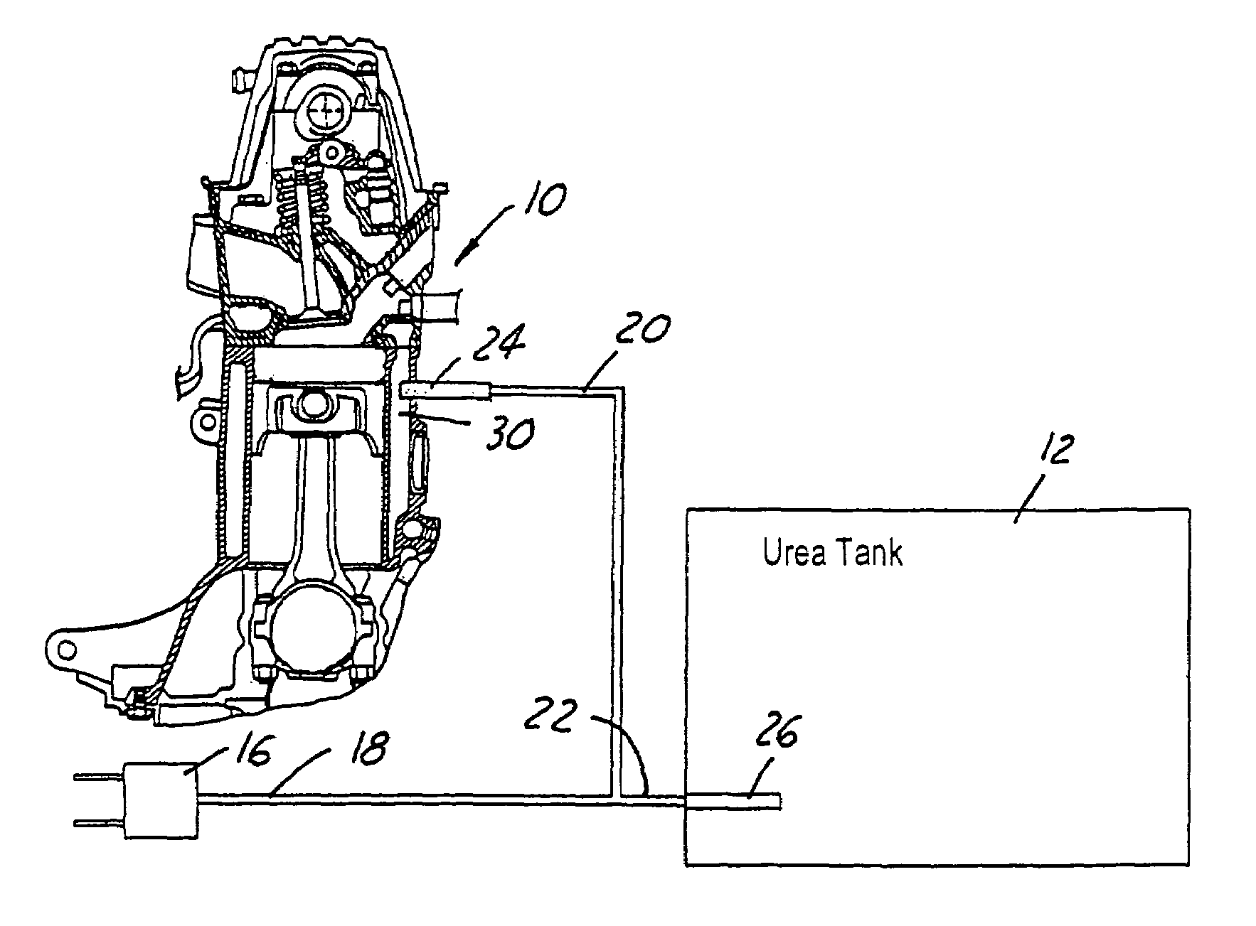
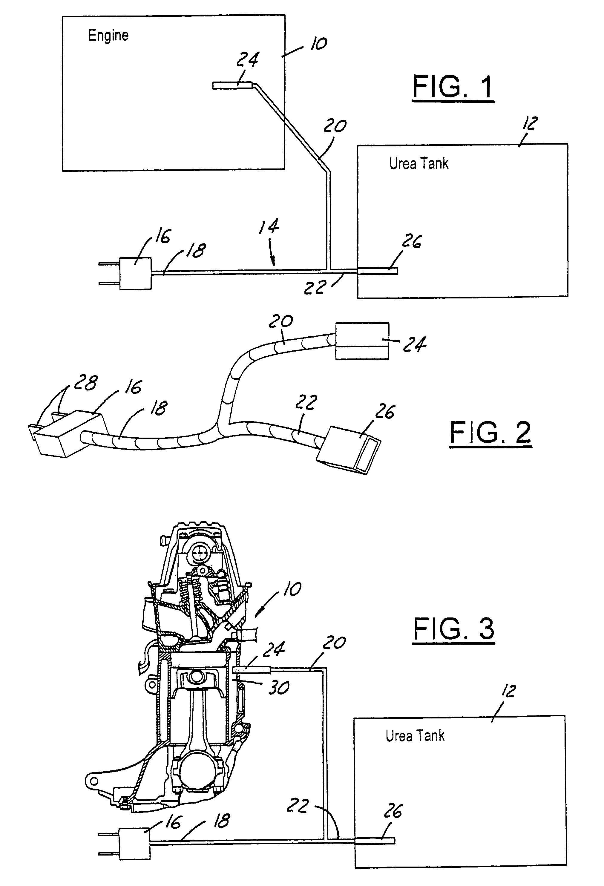
[0019]Referring now to FIG. 1, a diesel engine 10 for an automotive vehicle such as a truck is schematically illustrated along with a urea tank 12. The urea tank conventionally has a supply line that leads to the engine exhaust system (both not shown). An electrical power cord 14 has a plug 16 attached to a common distal end 18.

[0020]The cord 14 splits into two branches 20 and 22. Branch 20 is connected to a heater element 24 that is mounted into the engine 10. The branch 22 is connected to heater element 26 that is mounted within the urea tank 12.

[0021]As shown in FIG. 2, the branches 20 and 22 join in a Y joint to the common distal end 18. The plug 16 has conventional electrical prongs 28 that are constructed to be plugged into an electrical outlet such as a common place 120 volt AC receptacle.

[0022]The heater element 24 is desirably mounted in the water jacket 30 of the diesel engine 10 in a conventional fashion as shown in FIG. 3.

[0023]In this manner, heating of the urea tank is...


PUM


Abstract

A diesel engine (10) having a selective catalytic reduction system with a urea tank (12). A heater element (26) is mounted in the urea tank and another heating element (34) is mounted in the engine (10) for cold weather starts. Both heating elements (24) and (26) are connected to a common cord (18) which has at its distal end a common electrical plug (16) for plugging into an electrical receptacle.

Description

TECHNICAL FIELD[0001]The field of this invention relates to a selective catalytic reduction system for diesel engines using a urea solution and more particularly to a heater for the diesel engine block and urea tank.BACKGROUND OF THE DISCLOSURE[0002]Diesel engines have long been used in automotive application, particularly for larger truck applications. Because of the great popularity of diesel engines and extensive use with trucks on the highways and roads around the world, there have been tremendous efforts and great advances to reduce many air polluting emissions entering the environment as much as practical.[0003]Of the various emissions which have been identified for possible reduction, oxides of nitrogen commonly referred to as NOx emissions have been regulated by the United States Federal government. It has been known that selective catalytic reduction (SCR) is a very effective means to provide NOx reduction. Selective catalytic reduction has been known for stationary power a...

Claims


Application Information

Patent Timeline
IPC IPC(8): F01N3/20
CPCF01N3/2066Y02T10/24F01N2610/10F01N2610/02Y02T10/12
Inventor GOMULKA, TED GENE
Owner DETROIT DIESEL
Learn More