Fuel supply system for internal combustion engine

Inactive Publication Date: 2005-05-31
TOYOTA JIDOSHA KK
View PDF16 Cites 36 Cited by
  • Summary
  • Abstract
  • Description
  • Claims
  • Application Information

AI Technical Summary

Benefits of technology

[0006]Accordingly, the present invention has been made in view of the above-mentioned problems, and has for its object to provide a technique capable of keeping the fuel pressure constant in a fuel supply system for an internal combustion engine.

Problems solved by technology

However, in cases where an internal combustion engine is equipped with a plurality of fuel pumps, the pressure of fuel supplied by these fuel pumps is caused to vary when the number of operations of the fuel pumps is changed.
In addition, parts of fuel discharged from the respective fuel pumps might interfere with one another, so it would become difficult to suppress pulsations of the fuel pressure.
If the fuel pressure is varied in this manner, it becomes difficult to perform stable fuel injection.

Method used


Image

  • Fuel supply system for internal combustion engine
  • Fuel supply system for internal combustion engine
  • Fuel supply system for internal combustion engine

Examples


first embodiment

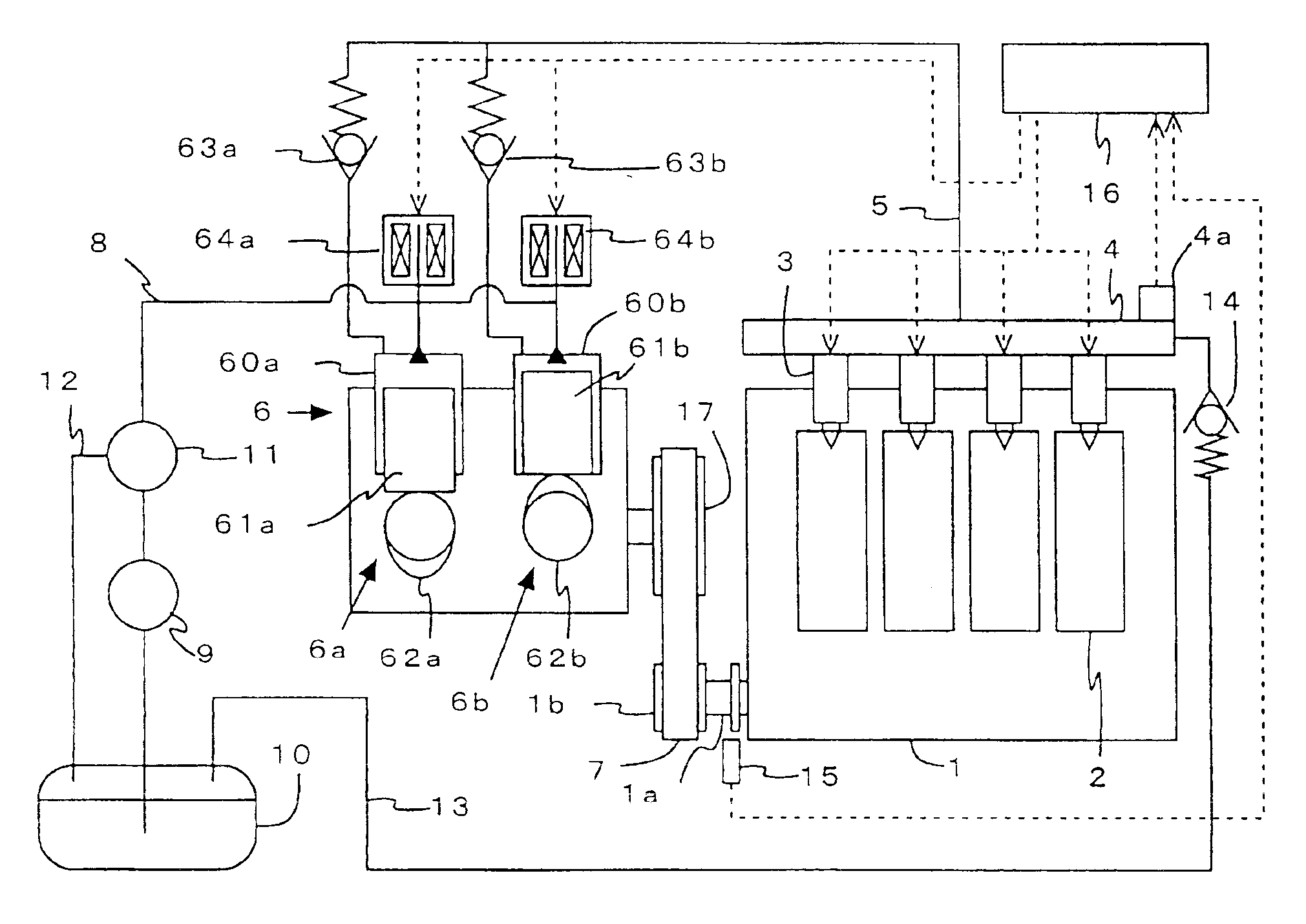
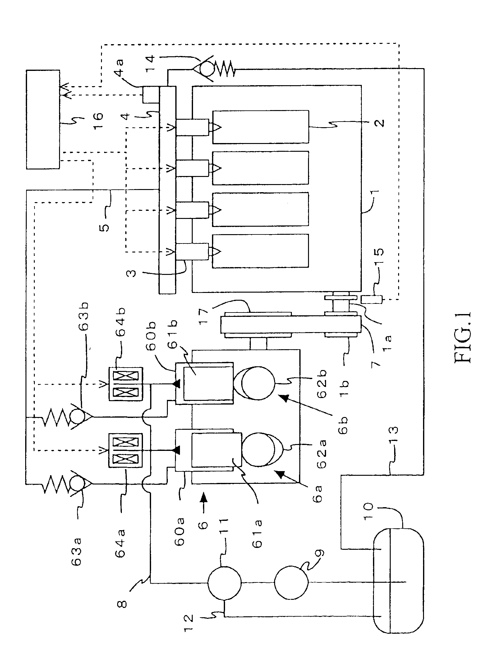
[0046]FIG. 1 is a view that shows the schematic construction of an internal combustion engine 1 with a fuel supply system applied thereto according to the present invention. In addition, FIG. 12 is a view that schematically shows the flow of control signals in the fuel supply system applied to the internal combustion engine 1.

[0047]The internal combustion engine 1 (hereinafter also referred to simply as an engine) as illustrated in FIG. 1 is a four-cycle gasoline engine having four cylinders 2.

[0048]The engine 1 is provided with four fuel injection valves 3, one for each cylinder 2, for directly injecting fuel into a combustion chamber of each cylinder 2. The fuel injection valves 3 are respectively connected with a delivery pipe 4 that serves to accumulate the fuel therein to a prescribed pressure. Mounted on this delivery pipe 4 is a fuel pressure sensor 4a for outputting a signal corresponding to the fuel pressure in the delivery pipe 4.

[0049]The delivery pipe 4 is in fluid commu...

second embodiment

[0112]Accordingly, in this second embodiment, the engine 1 is started with the electromagnetic valve 64a for the first fuel pump 6a being held in its open state, while bringing the second fuel pump 6b into operation.

[0113]FIG. 6 is a view that shows the operating states of the fuel pumps at the time of engine starting in the fuel supply system for an internal combustion engine according to the second embodiment of the present invention.

[0114]In this embodiment, the first fuel pump 6a is stopped but the second fuel pump 6b is operated at engine starting. The first fuel pump 6a in stopped state passes therethrough fuel discharged from the low pressure fuel pump 9, that is serves as a fuel passable pump. Here, the valve closure time or duration of the electromagnetic valve 64b is set longer at the time before the rotational speed of the engine increases above the prescribed value than at the time of engine idling operation. By so doing, it is possible not only to suppress the reduction...

third embodiment

[0125]Thus, according to the present invention, fuel piping is arranged such that fuel is delivered from one location of the communication pipe 600 to the respective delivery pipes so as to flow only in one direction, thereby making it possible to suppress the pulsation of the fuel pressure.

[0126]FIG. 9 is a view that shows the schematic construction of an internal combustion engine with a fuel supply system applied thereto according to the third embodiment of the present invention.

[0127]The internal combustion engine as illustrated in FIG. 9 is a four-cycle V-type gasoline engine having six cylinders 2.

[0128]The internal combustion engine is constructed to have a first bank 100a and a second bank 100b. In addition, a first fuel pump 6a is installed on the first bank 100a, and a second fuel pump 6b is installed on the second bank 100b. The first fuel pump 6a and the second fuel pump 6b are placed in fluid communication with each other by connecting their fuel outlets (discharge port...


PUM


Abstract

In a fuel supply system for an internal combustion engine, there is provided a technology capable of keeping the pressure of fuel constant. Fuel pumps are provided in which the pressure of fuel to be discharged therefrom can be adjusted due to an increase and a decrease in the amount of the fuel discharged, and the discharge of fuel therefrom can be stopped. Fuel injection valves serve as a fuel pressure reducing device that reduces the fuel pressure raised by the fuel pumps. A fuel pressure adjusting section changes the number of operations of the fuel pumps and the amounts of fuel discharged from the fuel pumps in such a manner that an average value of the fuel pressure from after the fuel pressure has once been raised until the fuel pressure is again raised becomes substantially constant before and after the number of operations of said fuel pumps is changed.

Description

BACKGROUND OF THE INVENTION[0001]1. Field of the Invention[0002]The present invention relates to a fuel supply system for an internal combustion engine.[0003]2. Description of the Related Art[0004]There have hitherto been known a variety of fuel supply systems for internal combustion engines, such as a technique of increasing and decreasing the number of operations of fuel pumps (i.e., the number of operating fuel pumps) according to the operating conditions of an internal combustion engine (for example, see a first patent document: Japanese patent application laid-open No. 03-9067 (pages 2, 3, and FIG. 2)), a technique of operating only one of fuel pumps at the time of engine starting (for example, see a second patent document: Japanese patent application laid-open No. 03-74564 (pages 3, 4, and FIGS. 3 and 4)), a technique of operating only one of fuel pumps at the time when the amount of fuel to be injected is limited (for example, see a third patent document: Japanese patent appl...

Claims


Application Information

Patent Timeline
IPC IPC(8): F02M63/02F02M63/00F02D41/38F02M37/00F02D33/00F02D41/14F02D41/40F02M51/00F02M55/02
CPCF02D33/003F02D41/3845F02M63/0225F02D2250/31F02M37/0047F02D2200/0602
Inventor MIYASHITA, SHIGEKI
Owner TOYOTA JIDOSHA KK
Why Eureka
Try Eureka