
Information recording medium with index header

a technology of information recording and index header, which is applied in the field of information recording medium, can solve the problems of long time required to make the disk cope with a frequency change, long time required to reduce the transfer rate, and make seamless recording difficult, etc., and achieve the effect of high recording efficiency

Inactive Publication Date: 2005-05-24
KK TOSHIBA
View PDF10 Cites 22 Cited by
  • Summary
  • Abstract
  • Description
  • Claims
  • Application Information

AI Technical Summary

Benefits of technology

[0013](1) an information recording medium with high recording efficiency and, more particularly, an information recording medium which can record a large amount of continuous data such as video data and also small fragments of data in units of ECC blocks such as PC data at arbitrary positions;
[0014](2) an information recording apparatus and method which can record information on an information recording medium with high recording efficiency and, more particularly, an information recording medium which can record a large amount of continuous data such as video data and also small fragments of data in units of ECC blocks such as PC data at arbitrary positions so as to utilize features of the information recording medium; and
[0015](3) an information reproduction apparatus and method which reproduce information recorded on an information recording medium with high recording efficiency and, more particularly, an information recording medium which can record a large amount of continuous data such as video data and also small fragments of data in units of ECC blocks such as PC data at arbitrary positions.
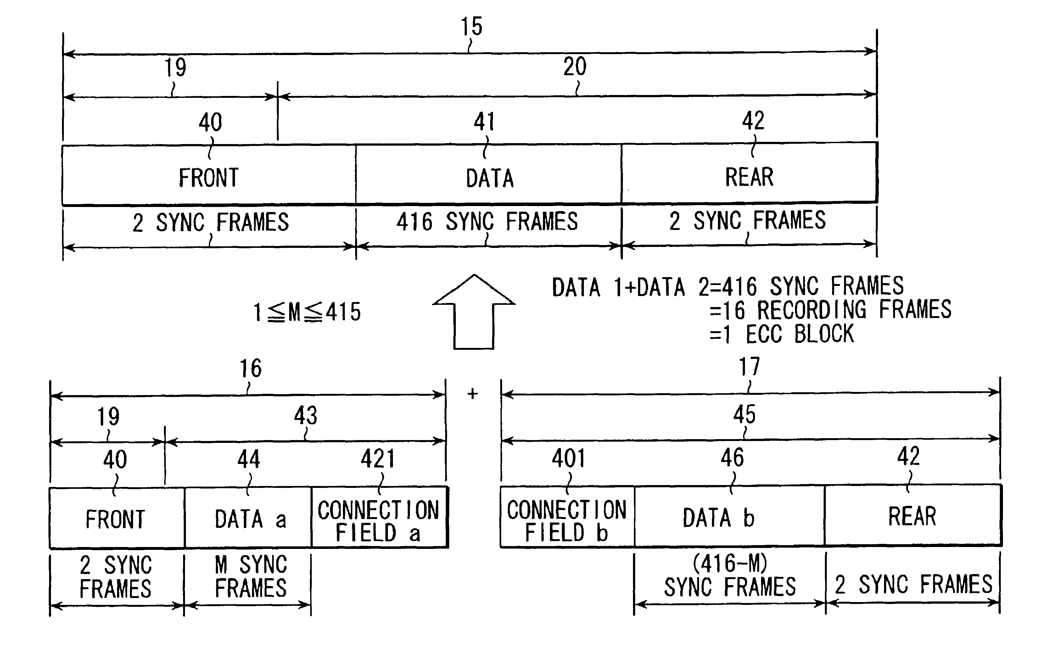
[0023]Upon recording data for the first time without physically formatting a disk, address data of physical tracks are read out from index headers each of which is located at one position per round. The physical position within one round is accurately determined by counting from the index header. Theoretically, data is recorded in units of ECC blocks. However, in practice, a header field including address data and data field including an ECC block are recorded together in one recording field. The header field is never rewritten unless the disk is re-formatted. Upon rewriting on a disk on which data has already been recorded, only the data field is rewritten. In an optical disk of phase change recording scheme, as in a DVD-RAM, the data field has a gap as measures against deterioration of the leading and trailing edges, and a buffer for absorbing eccentricity and rotational variation. Since the rotational speed and recording frequency of the disk are obtained from wobbles, the buffer area can be minimized.
[0025]Therefore, according to the present invention, even before an optical disk is physically formatted, ECC block data can be accurately written at an arbitrary physical address, and both continuous and random data can be efficiently recorded. Since data are recorded in units of ECC blocks, a portion other than data can be minimized compared to a DVD-RAM on which data are recorded in units of sectors. That is, the information recording medium of the present invention has higher recording efficiency than the DVD-RAM. Since no embossed pits are required to be aligned in the radial direction at very small intervals (sector field intervals), the number of zones can be greatly increased. In this manner, a change in frequency between neighboring zones can be smaller than a change in allowable recording density or allowable rotational variation, thus allowing seamless recording across different zones.

Problems solved by technology

For this reason, when data such as video data are to be recorded in a large quantity, a long time is required to make the disk cope with a change in frequency.
Such long time decreases the transfer rate and makes seamless recording difficult.
For this reason, high-precision embossed pit recording is required, and it is difficult to adjust an optical head to precisely reproduce embossed pits, resulting in an increase in cost.
In these disks, it is difficult to efficiently record data at arbitrary positions.
Such recording scheme is suitable for recording continuous data such as video data, but is not suitable for recording small fragments of data such as computer data.
As described above, when the conventional optical disk recording scheme adopts a format suitable for recording random data, such format results in recording efficiency drop or is not suitable for continuous recording.
Conversely, when a format suitable for continuous recording is adopted, it is not suitable for recording random data.

Method used


Image

  • Information recording medium with index header
  • Information recording medium with index header
  • Information recording medium with index header

Examples


Embodiment Construction

[0045]A preferred embodiment of the present invention will be described hereinafter with reference to the accompanying drawings.

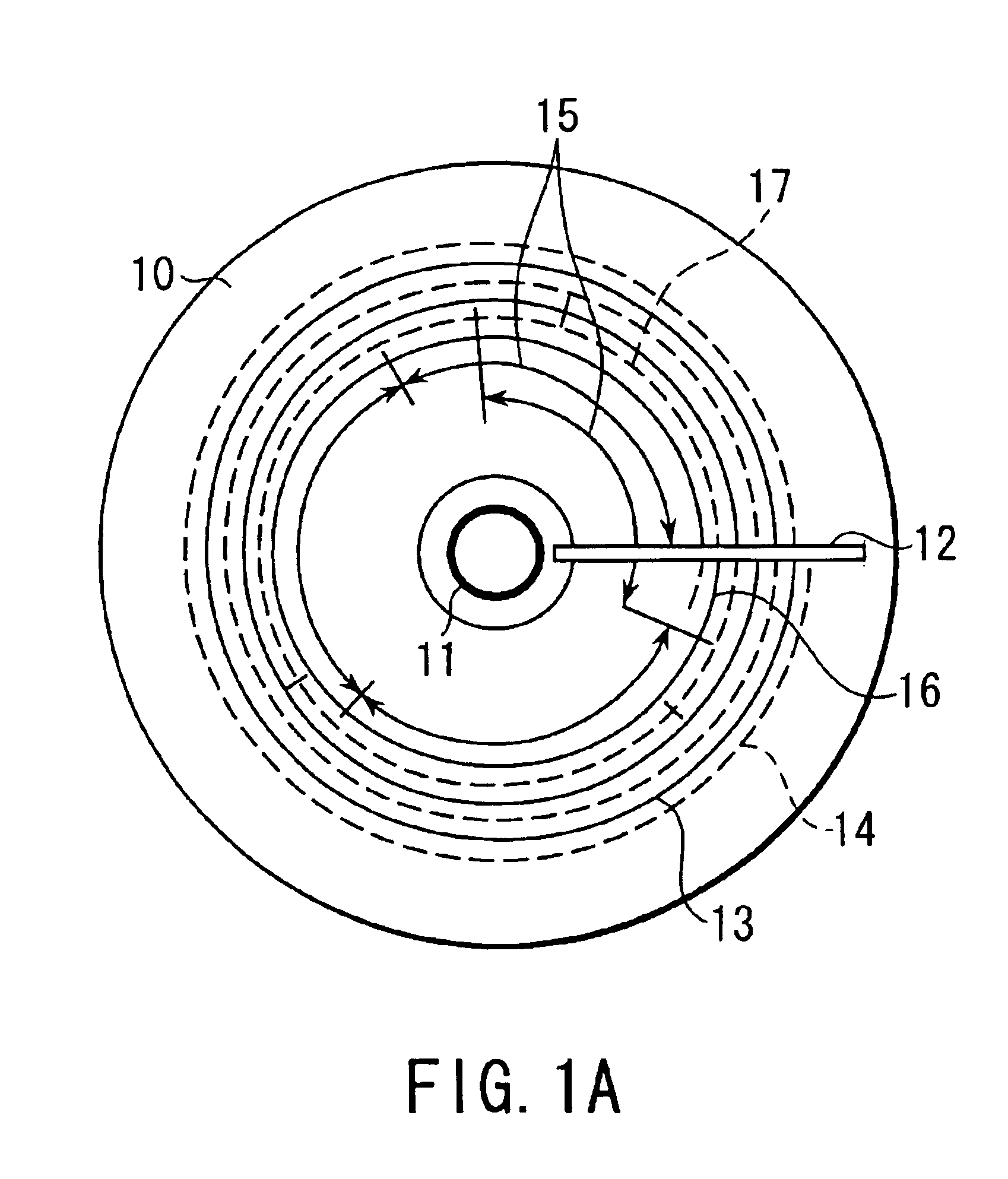
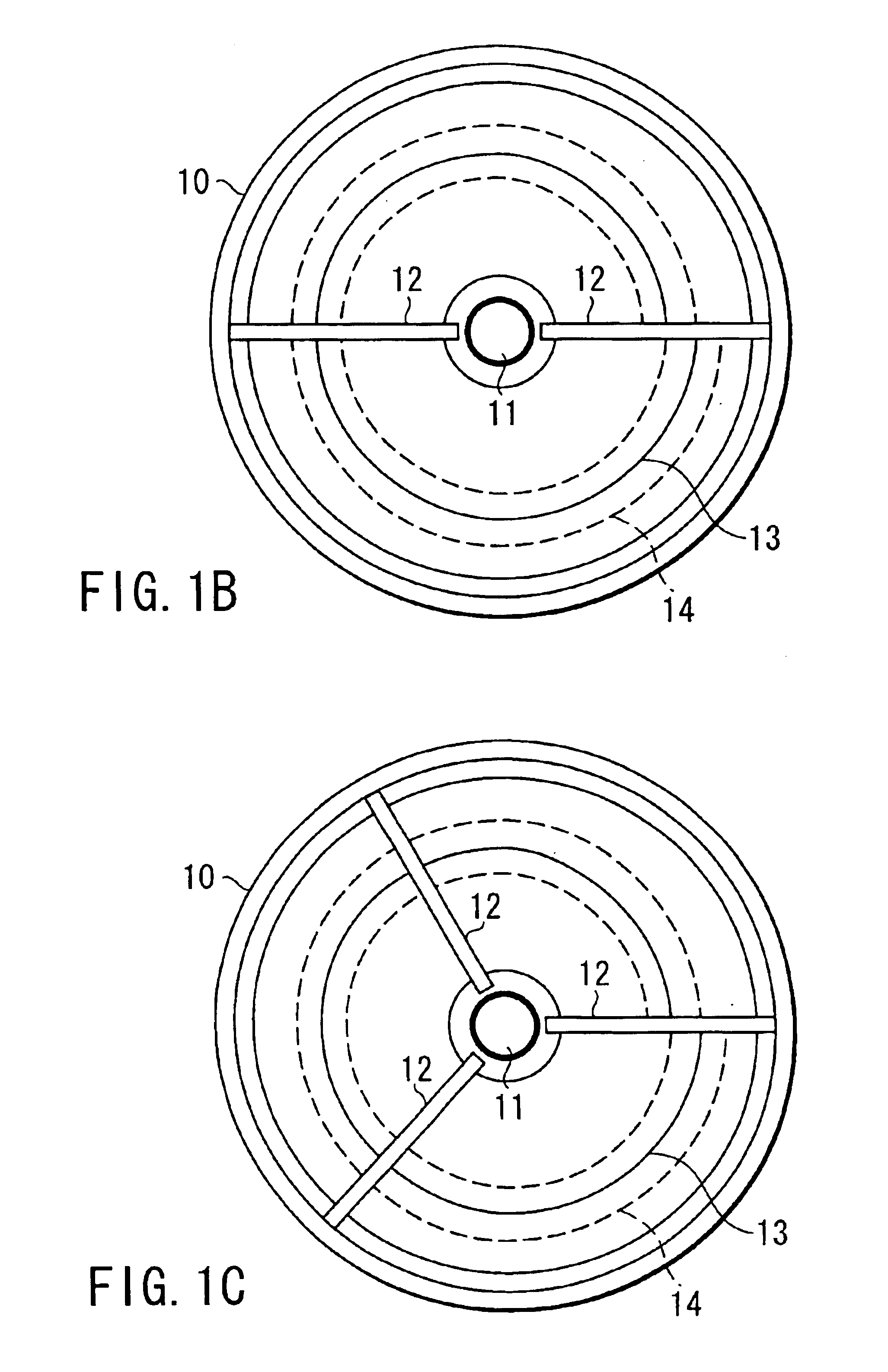
[0046]A rewritable optical disk according to an embodiment of an information recording medium of the present invention will be described below. FIG. 1 shows the overall optical disk, FIG. 2 shows the track structure of the optical disk, FIG. 3 shows an example of an index header, FIG. 4 shows an example of a recording field, FIG. 5A shows the relationship between the recording field and sub recording fields and also the data structure (with a connection field) of the sub recording fields, FIG. 5B shows an example of the structure of the connection field in the sub recording field, and FIG. 5C shows the relationship between the recording field and sub recording fields and also the data structure (connection field structure equal to FRONT or REAR structure) of the sub recording fields.

[0047]As shown in FIG. 1, an optical disk 10 has spiral tracks (recording t...


PUM


Abstract

A disk-shaped information recording medium has spiral tracks in which land- and groove-shaped tracks are alternately switched in units of rounds, and one index header which is aligned in the radial direction of a disk and is allocated at only the boundary between the land- and groove-shaped tracks.

Description

CROSS-REFERENCE TO RELATED APPLICATIONS[0001]This application is based upon and claims the benefit of priority from the prior Japanese Patent Application No. 11-336613, filed Nov. 26, 1999, the entire contents of which are incorporated herein by reference.BACKGROUND OF THE INVENTION[0002]The present invention relates to an information recording medium such as a rewritable optical disk or the like. The present invention also relates to an information recording apparatus and method for recording information on an information recording medium such as a rewritable optical disk or the like. Furthermore, the present invention relates to an information reproduction apparatus and method for reproducing information recorded on the rewritable information recording medium.[0003]In recent years, rewritable optical disks on which data can be randomly recorded have been extensively studied and developed. Of such disks, a rewritable optical disk called a DVD-RAM having a diameter of 120 mm is know...

Claims


Application Information

Patent Timeline
IPC IPC(8): G11B20/12G11B7/007G11B27/24
CPCG11B7/00745G11B20/1217G11B27/24G11B2020/1225G11B2220/2575G11B2020/1239G11B2020/1287G11B2220/2537G11B2020/1238
Inventor SUGAYA, TOSHIHIROHASEGAWA, HIROSHI
Owner KK TOSHIBA
Learn More