
Water pressured destruct enhancer

a technology of enhancer and water cannon, which is applied in the direction of dental surgery, lighting and heating apparatus, combustion types, etc., can solve the problems of reducing the forward speed of the jet, bursting of the diaphragm, and the jet of water from the device, so as to improve the performance of the system, improve the penetration of the item, and focus more energy

Inactive Publication Date: 2005-05-24
THE UNITED STATES OF AMERICA AS REPRESENTED BY THE SECRETARY OF THE NAVY
View PDF12 Cites 32 Cited by
  • Summary
  • Abstract
  • Description
  • Claims
  • Application Information

AI Technical Summary

Benefits of technology

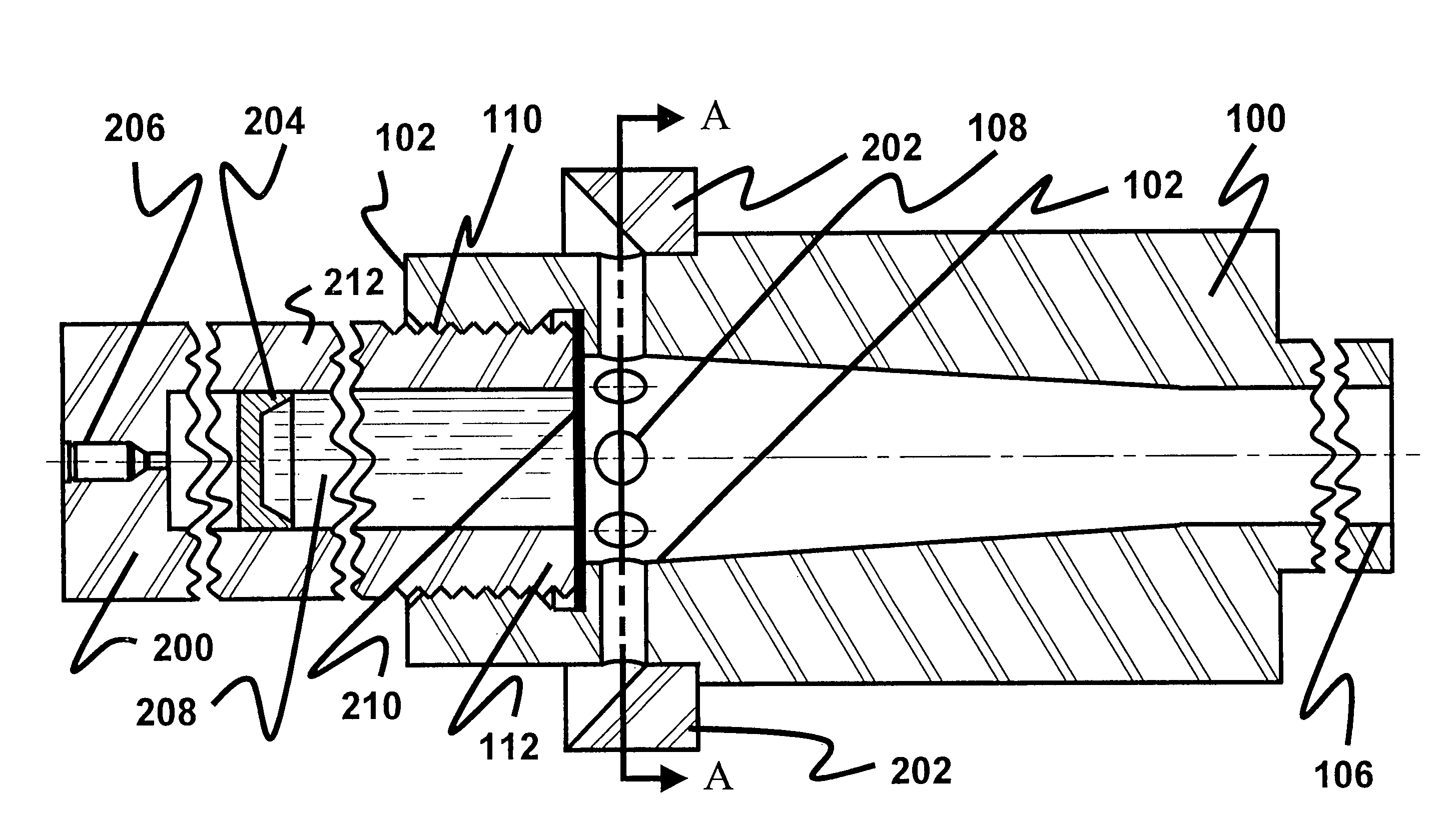
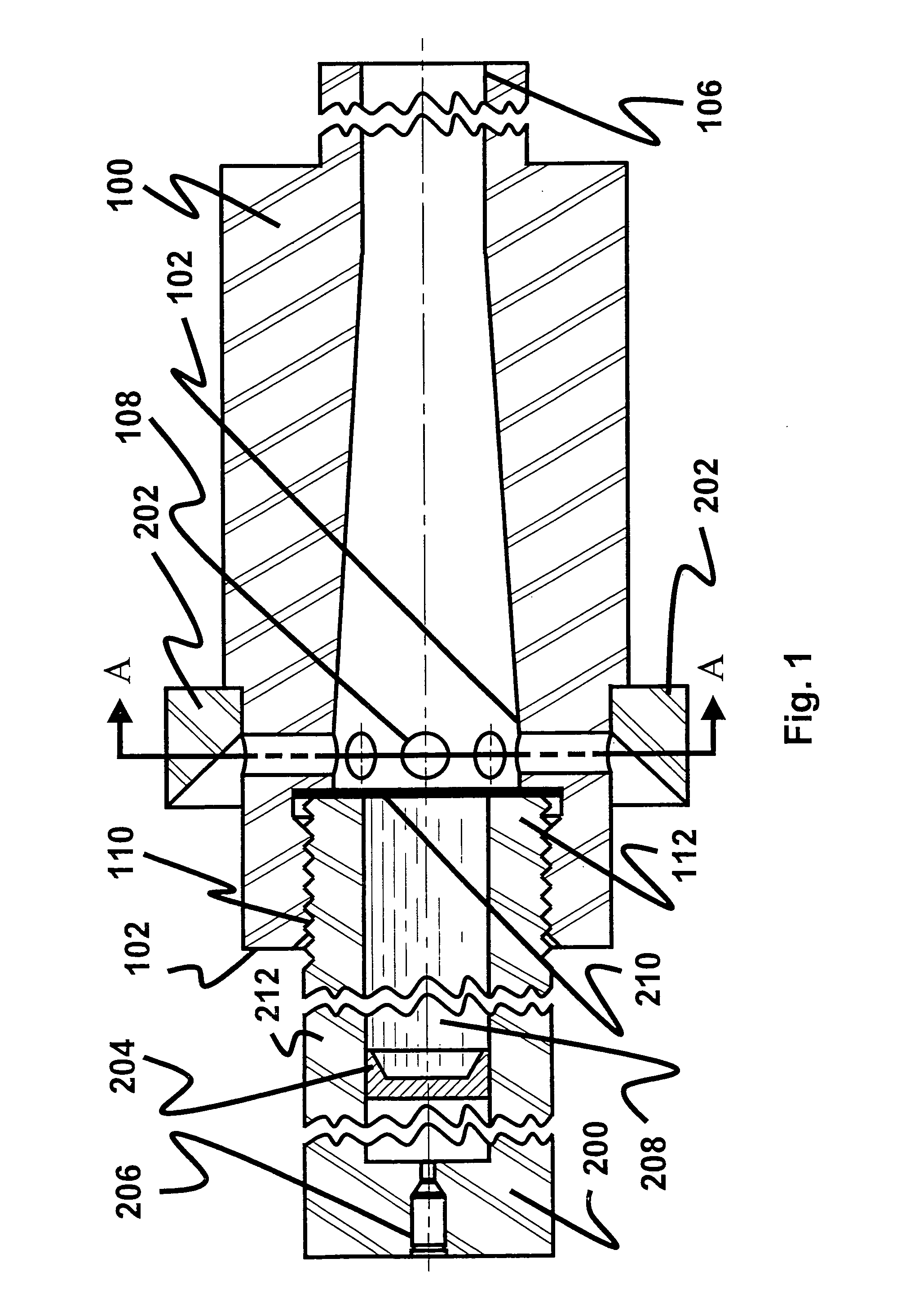
[0009]The extension tube as herein described will provide a more uniform jet of water with more focused energy by containing the jet until breech pressures are vented. Better control of the water jet will be maintained during firing operations. Further, more energy may be put into the water jet to accomplish specific tasks. These advantages will allow better penetration of the item on which the device is used. Also, for procedures involving rendering safe improvised explosive devices, this invention will allow the operator to set up the water based device at a position that is further away from the explosives.
[0010]Accordingly, it is the object of this invention to provide a device which improves the performance of systems that dispense jets of water.
[0011]It is a further object of this invention to provide a device to increase the length of the water jet stream of systems that produce such water jet streams.

Problems solved by technology

When pressure is applied to the pusher plate or piston, the burst diaphragm ruptures and a jet of water issues from the device.
However, because the back portion of the water slug in the JROD, and other water disrupt devices, remains in the bore and is still being accelerated after the front portion of the water slug begins to jet out of the bore, it tends to push against the jet that has left the bore.
This tends to distort, degrade, and brake-up the jet causing the jet to disperse relatively quickly after leaving the bore and result in a reduced forward speed of the jet.

Method used


Image

  • Water pressured destruct enhancer
  • Water pressured destruct enhancer
  • Water pressured destruct enhancer

Examples


Embodiment Construction

[0018]The invention, as embodied herein, comprises an improvement to devices that produce a jet of water having a water slug, a bore end and an outlet diameter associated with the bore end. In one configuration, such a device comprises a slug of water contained within a tube between a burst diaphragm and an obturated pusher plate or piston. When pressure is applied to the pusher plate or piston, the burst diaphragm ruptures and a jet of water issues from the device. Pressure to the pusher plate or piston is normally applied by burning a gun propellant that is housed in a cartridge or as a breech charge.

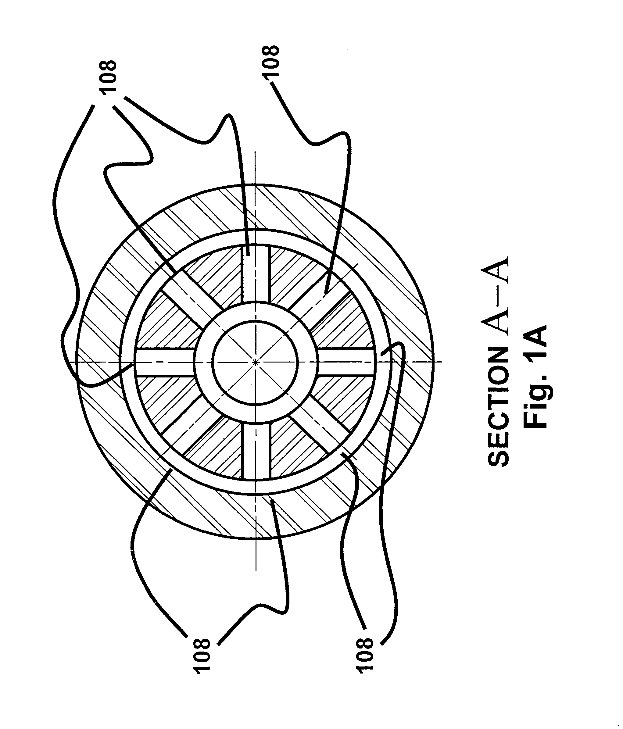
[0019]The improvement comprises an extension tube having a volume sufficient to hold the entire water slug and a means for attaching the extension tube to the bore end of the device. The extension tube having first and second ends, wherein the first end comprises a location proximate to the attaching means and comprises an inner diameter greater than the inner diameter of the outlet o...


PUM


Abstract

The present invention comprises an extension tube that attaches to the bore end of a water jet producing device that is used to render safe improvised explosive devices by disrupting the firing train of said devices. The present invention comprises an extension tube having a sudden enlargement of cross section, that may be formed by adjusting the dimensions of the interior diameter of the extension tube, at the point of attachment, and a series of apertures in the attachment tube. The extension tube provides a more uniform jet of water with more focused energy by containing the jet until breech pressures are vented. Better control of the water jet will be maintained during firing operations. Further, more energy may be put into the water jet to accomplish specific tasks.

Description

PRIORITY STATEMENT[0001]This application is a continuation-in-part of application Ser. No. 10 / 055,254, filed on Jan. 24, 2002, now abandoned, which was a continuation application of application Ser. No. 09 / 606,164, filed on Jun. 29, 2000, now abandoned.STATEMENT OF GOVERNMENT INTEREST[0002]The invention described herein may be manufactured and used by or for the Government of the United States of America for governmental purposes without payment of any royalties thereon or therefor.BACKGROUND OF THE INVENTION[0003]1. Field of the Invention[0004]The present invention pertains to an improvement in water cannons, and more particularly to water cannons used to render safe explosive devices. The present invention improves the performance of such systems, particularly related to their use to render safe explosive devices.[0005]2. Description of the Related Art[0006]Presently, devices using water to disrupt detonation of explosive devices are widely used. This is because of the relatively ...

Claims


Application Information

Patent Timeline
IPC IPC(8): A62C13/62A62C13/00F42B33/06
CPCF41B9/0075F42B33/062F41B9/0087
Inventor GREENE, MICHAEL L.DEVANE, SAMUEL J.
Owner THE UNITED STATES OF AMERICA AS REPRESENTED BY THE SECRETARY OF THE NAVY
Learn More