
Continuous severe plastic deformation process for metallic materials

a plastic deformation and continuous technology, applied in metal extrusion, extrusion dies, manufacturing tools, etc., can solve the problems of high density of steel, low tensile strength, and inability to adapt to stamping automobile body parts, so as to reduce the friction between the billets

Inactive Publication Date: 2005-05-24
DATRON INTERCONTINENTAL MFG +3
View PDF16 Cites 48 Cited by
  • Summary
  • Abstract
  • Description
  • Claims
  • Application Information

AI Technical Summary

Benefits of technology

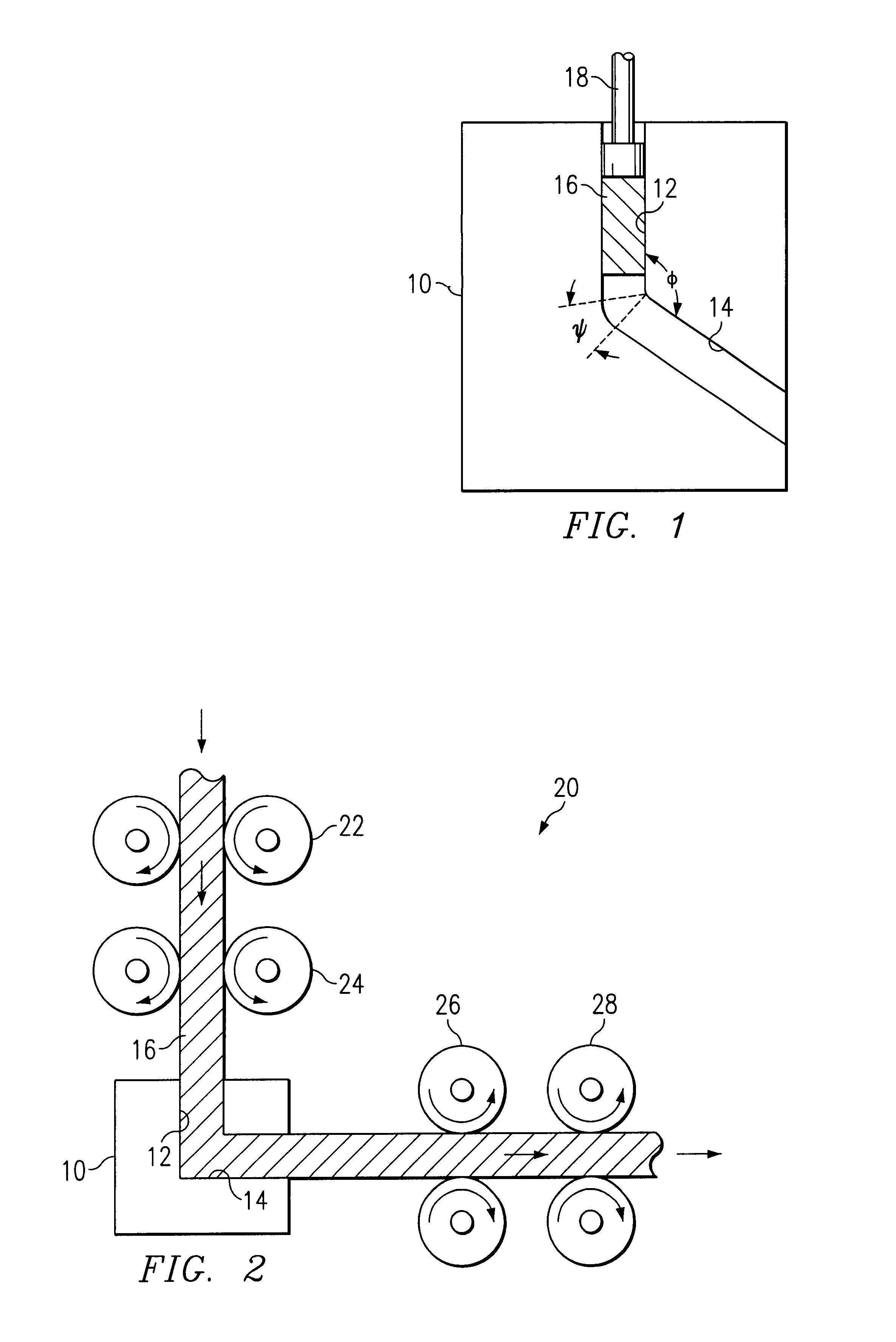
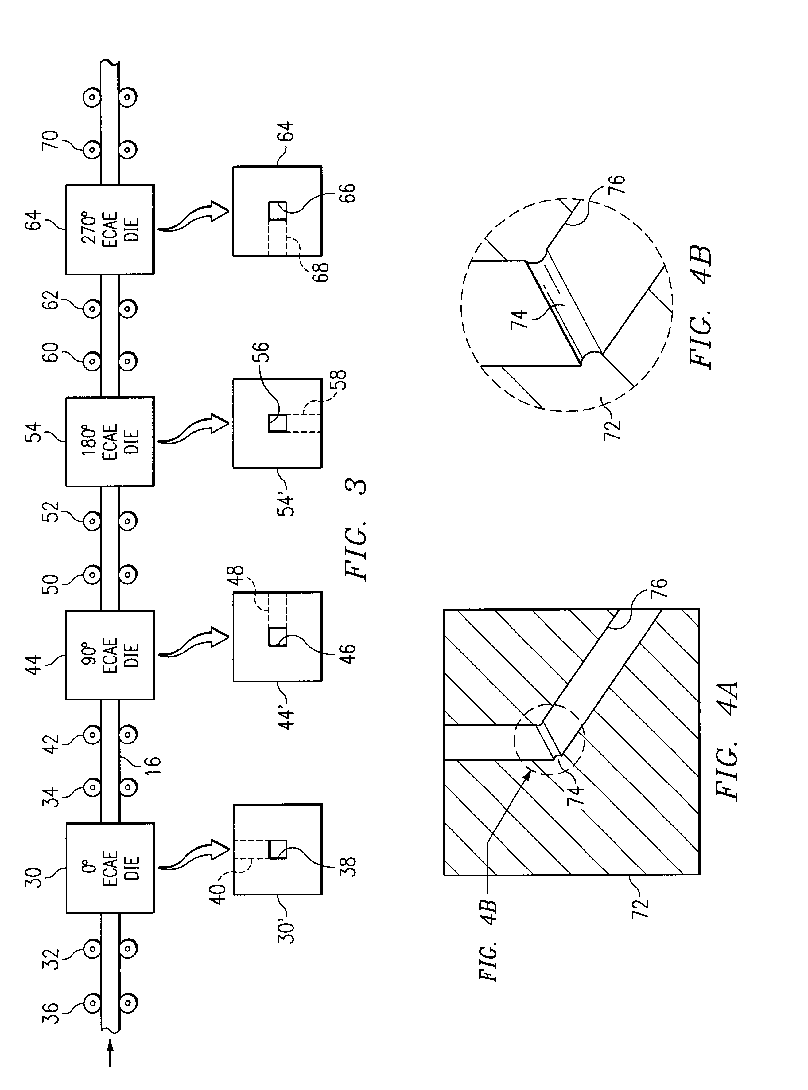
[0007]Disclosed is a method of fabricating ultrafine grain-hardened metals using a Continuous Severe Plastic Deformation (CSPD) method, where the process is carried out on a continuous or semi-continuous basis so that longer and larger billets of ultrafine grain, hardened metals can be produced. The CSPD dies are very similar to the ECAE / P dies but with different channel diameter / length ratios. The channel lengths of the CSPD dies are made shorter to reduce the friction between the billet and the CSPD die. In accordance with the principles and concepts of the invention, large and / or long billets of a metal are continuously fed to one or more CSPD dies arranged in a series. In a preferred form of the invention, the raw billets are continuously fed to a CSPD die by a set of push / pull rolls that grip or roll the billet and force it through the die. The set of push rolls are arranged on opposing sides of the long billet for gripping or rolling the billet and for pushing the billet into the die. The pull rolls also grip or roll the billet in a similar manner and are arranged to pull the billet from the die. Hence, the rolls can operate on continuous lengths of billets to thereby allow much longer billets of processed metals to be produced. When employed in a series of dies, the pull rolls of one die station can also function as the push rolls for the next downstream die station. The downstream dies are oriented in such a way that they can provide the effect of rotating the continuous billet in a desired angle as it is moved through the CSPD dies in a sequence. These die orientations can be changed in a manner so that the process can produce either equiaxed or elongated microstructure metals.
[0009]According to one aspect of the invention, there is disclosed a method of processing metallic materials by severe plastic deformation thereof, comprising the steps of providing at least one die with an angled bore through which a billet of the metallic material is moved, where the angled bore is structured so that the billet undergoes a severe plastic deformation when moved therethrough, and using a transport mechanism for gripping a side surface of the billet and moving the billet through the die, whereby a long length billet can be processed.
[0010]According to another aspect of the invention, there is disclosed a method of processing metallic billets by severe plastic deformation thereof, comprising the steps of providing at least a first and second die for causing severe plastic deformation of the billets when moved through the respective dies, arranging the dies in series such that at least a portion of the billet being processed is positioned in both said dies at the same time, and moving the billet simultaneously through said first and second dies so that severe plastic deformation of the billet occurs at different locations thereof at the same time, whereby long length billets can be processed.

Problems solved by technology

However, steel has a high density and is not suitable for lightweight applications such as those in the aerospace industry.
Aluminum, on the other hand, is light weight, but has a lower tensile strength, as compared to steel, and is not easily formable in sheet form, and is thus not well adapted for use in stamping automobile body parts.
These metals can thus be used in many other applications which heretofore rendered them unacceptable.
With a limitation of short billets, in connection with the diameter / length ratios noted above, there is inherently a substantial amount of waste associated with the process, it being realized that the frontal end and rear end parts of each billet may be unusable.
Hence, where the fabrication of large metal work pieces is necessary, the use of ECAE / P processed metals is not presently economically feasible.

Method used


Image

  • Continuous severe plastic deformation process for metallic materials
  • Continuous severe plastic deformation process for metallic materials
  • Continuous severe plastic deformation process for metallic materials

Examples


Embodiment Construction

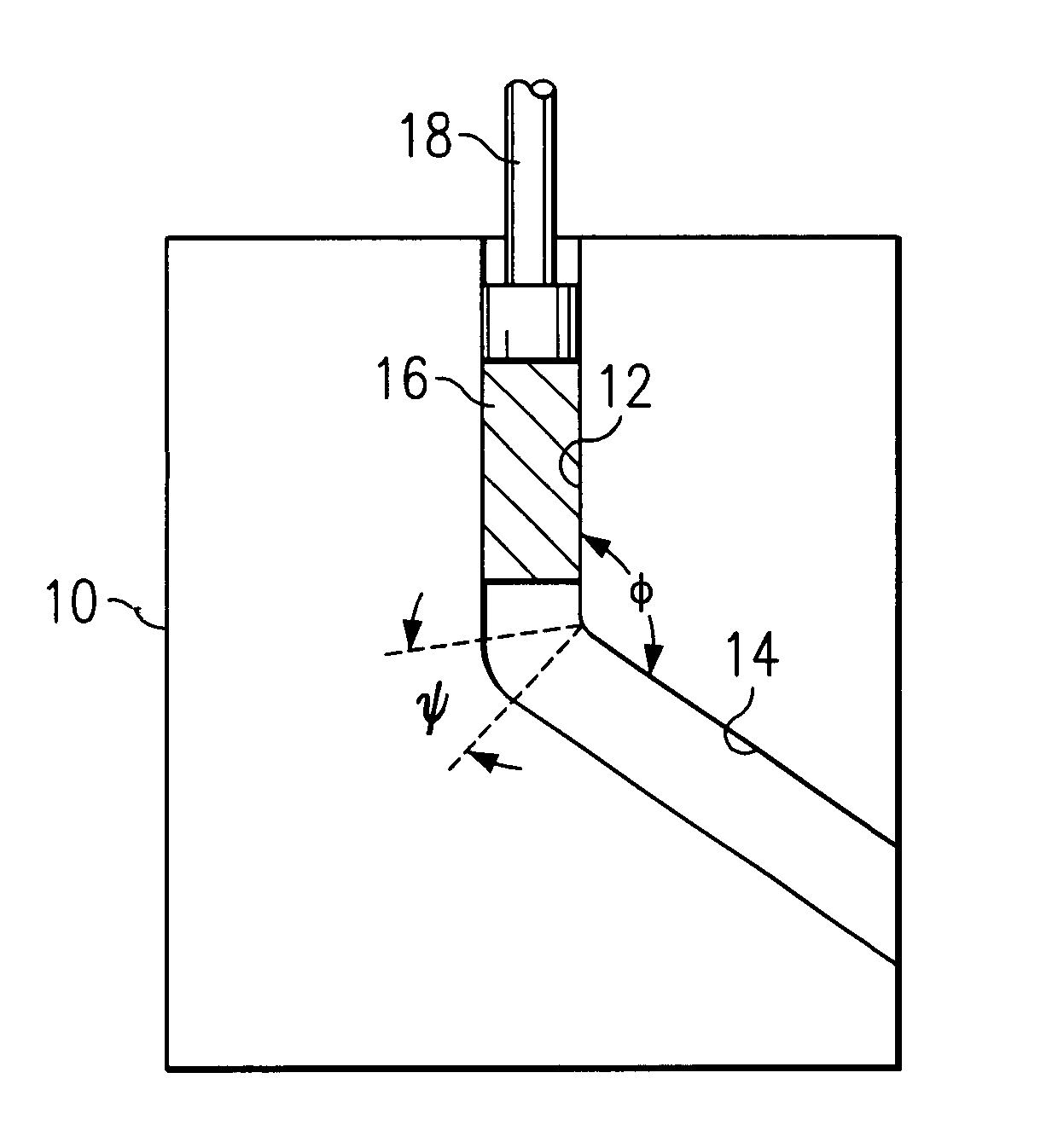
[0021]With reference now to FIG. 2, there is illustrated an embodiment showing the principles and concepts of the invention. A Continuous Sever Plastic Deformation (CSPD) die 10 is constructed with an internal path having an angle (Φ) of about 90 degrees, although any other angle can be employed. The CSPD die 10 may be of a construction the same or similar to a conventional ECAE / P die shown in FIG. 1, although it is preferable to construct the CSPD die 10 with a channel diameter / length ratio in the range of about 1:1 to about 1:2. With such type of die ratios, there is much less friction between the billet 16 and the die 10. By using a CSPD die 10 having a 90 degree angle between the entry channel 12 and the exit channel 14, a maximum shear strain equivalent to a tensile strain of about 1.0 can be achieved. Importantly, the billet 16 need not be short, as was required when using a ram-type force to move the billet 16 through the die. Rather, the billet 16 is constrained and carried ...


PUM

PropertyMeasurementUnit
Lengthaaaaaaaaaa
Angleaaaaaaaaaa
Angleaaaaaaaaaa

Abstract

A method of processing a billet of metallic material in a continuous manner to produce severe plastic deformation. The billet is moved through a series of CSPD dies in one operation to efficiently produce a billet characterized by a controlled grain structure. The long billets of metal stock are moved along the processing path through the CSPD dies with plural sets of pinch rolls which grip the billet and push it into the entry channel of the dies. Other sets of pinch rolls pull the billet from the exit channel of the dies.

Description

TECHNICAL FIELD OF THE INVENTION[0001]The present invention relates in general to the processing of metallic materials, and more particularly to a method of fabricating continuous or semi-continuous billets or bars of metallic materials using severe plastic deformation techniques.BACKGROUND OF THE INVENTION[0002]The metal industry continues to require new materials for fabricating products that are improved in performance and are less costly to manufacture. Because of the vast differences in the characteristics of metals themselves, some materials are uniquely adapted for special uses. Steel, for example, has a high characteristic tensile strength and is easily formable in sheet form and thus is well adapted for stamping automobile body parts as well as a host of other commercial and consumer goods. However, steel has a high density and is not suitable for lightweight applications such as those in the aerospace industry. Aluminum, on the other hand, is light weight, but has a lower ...

Claims


Application Information

Patent Timeline
IPC IPC(8): B21C33/00B21C35/00B21C23/00B21C25/00B21C25/02
CPCB21C23/00B21C23/001B21C35/00B21C25/02B21C33/00B21C23/005
Inventor CHAUDHURY, PRABIR K.SRINIVASAN, RAGHAVANVISWANATHAN, SRINATH
Owner DATRON INTERCONTINENTAL MFG
Learn More