
Method for providing a pressurized fluid

a technology of pressurized fluid and liquid, which is applied in the direction of nuclear engineering, greenhouse gas reduction, nuclear elements, etc., can solve the problems of more difficult management than a simple flow of liquid, and achieve the effect of high operating reliability

Inactive Publication Date: 2005-05-17
AREVA GMBH
View PDF17 Cites 12 Cited by
  • Summary
  • Abstract
  • Description
  • Claims
  • Application Information

AI Technical Summary

Benefits of technology

[0009]It is accordingly an object of the invention to provide a method for providing a pressurized fluid that overcome the above-mentioned disadvantages of the prior art devices and methods of this general type, in which a high operating reliability is ensured.

Problems solved by technology

However, the fluid dynamics of a two-phase flow of this nature makes it more difficult to manage than a simple flow of liquid.

Method used


Image

  • Method for providing a pressurized fluid
  • Method for providing a pressurized fluid
  • Method for providing a pressurized fluid

Examples


Embodiment Construction

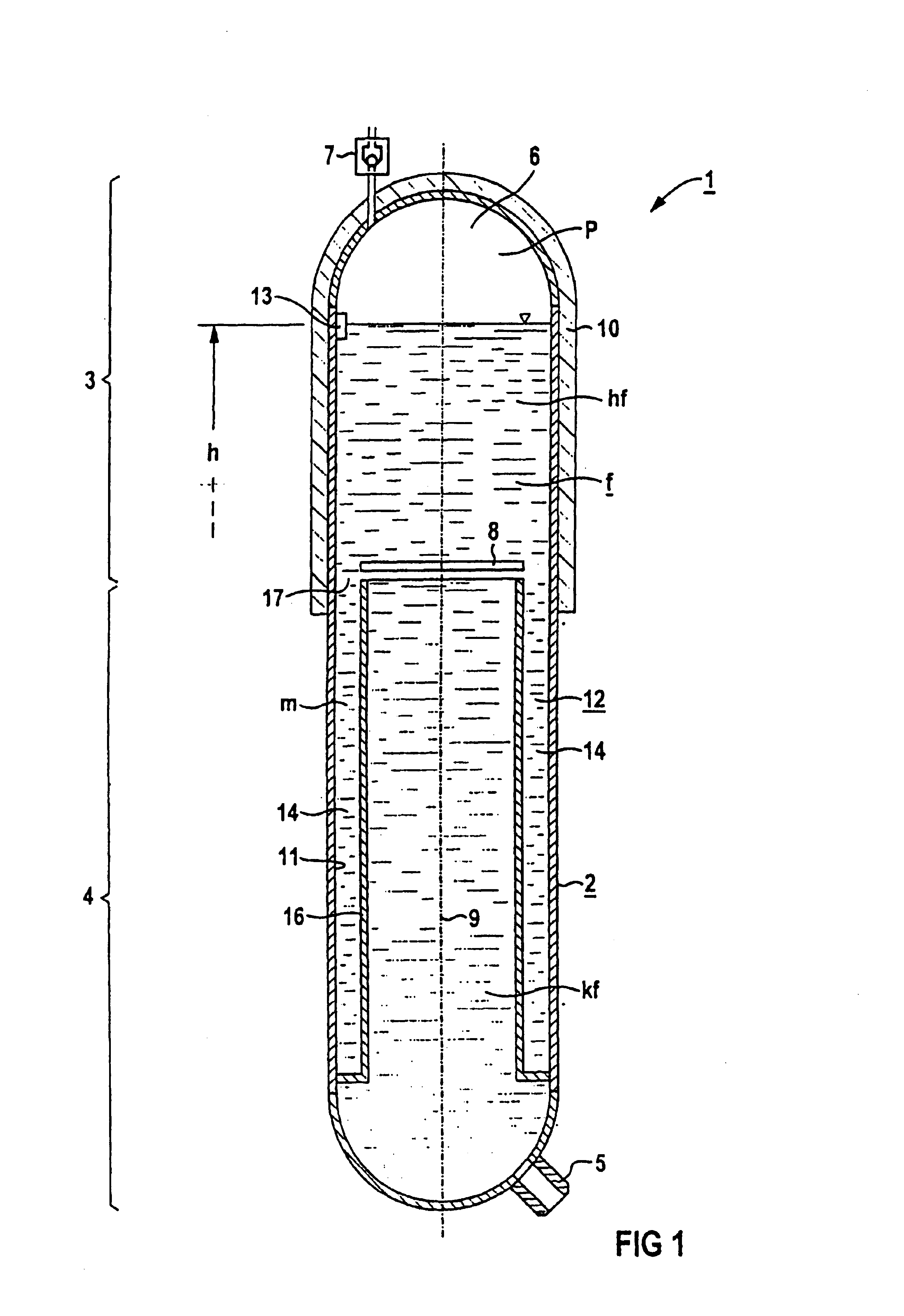
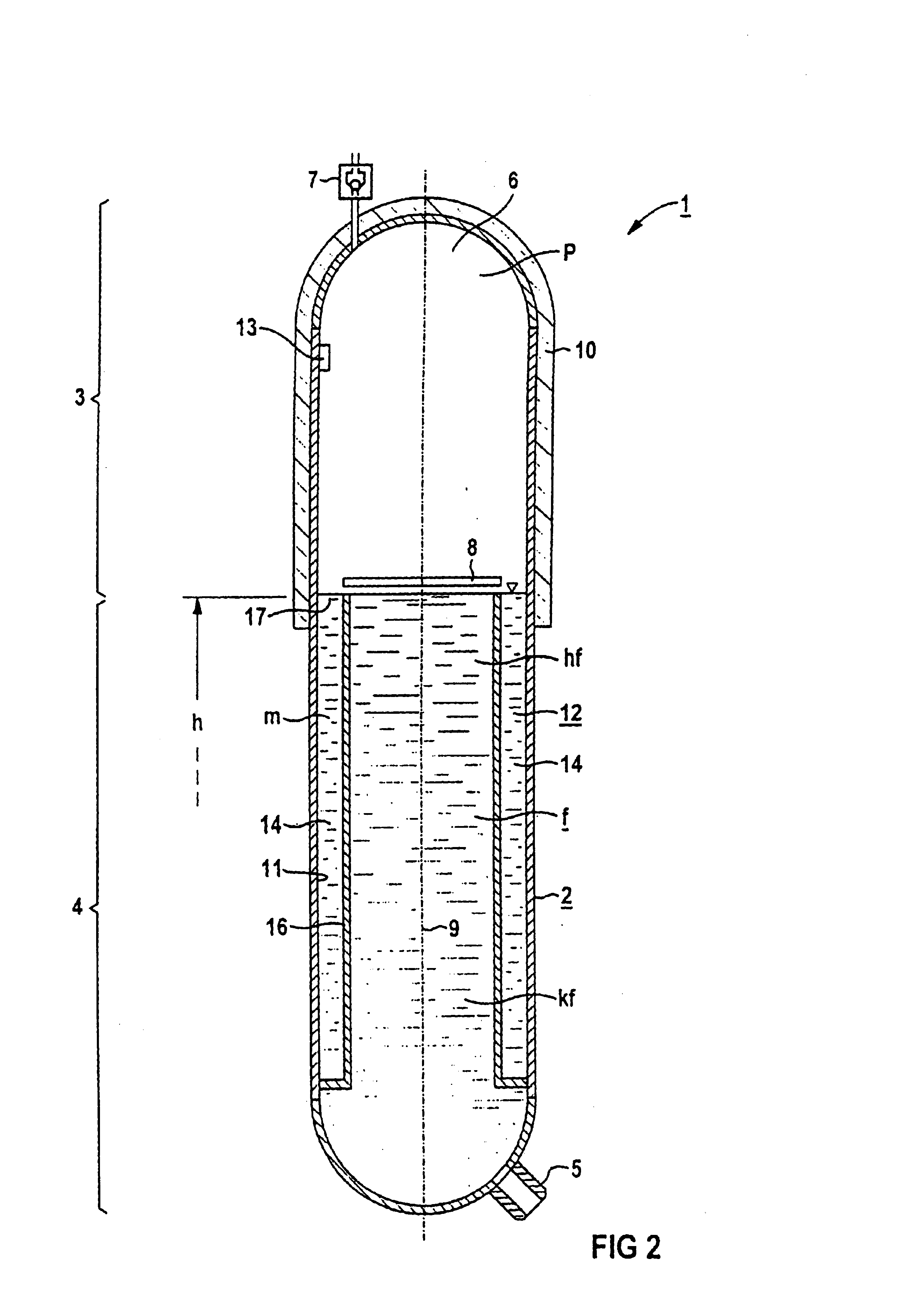
[0039]In all the figures of the drawing, sub-features and integral parts that correspond to one another bear the same reference symbol in each case. Referring now to the figures of the drawing in detail and first, particularly, to FIG. 1 thereof, there is shown a pressure accumulator 1. The pressure accumulator 1 contains a closed, upright vessel 2 having an upper region 3 and a lower region 4 that is about ⅔ of the volume of the vessel. The vessel 2 is filled with a fluid f up to a filling level h. A level meter 13 is provided in order to accurately set the filling level h while the pressure accumulator 1 is being filled with the fluid f and to monitor the filling level h during the standby mode. In accordance with FIG. 1, the level meter 13 is a sensor that measures whether the desired filling level h is maintained. Alternatively, the level meter 13 may also be formed, for example, in the manner of a communicating tube as a riser that is in communication with the pressure accumula...


PUM


Abstract

In order, in a pressure accumulator, to generate a required operating pressure of a fluid situated in the pressure accumulator, a heater device is provided, disposed in an upper region of the pressure accumulator. The device generates a vapor cushion and the required operating pressure. Where necessary, when the fluid flows out, the pressure in the pressure accumulator is automatically reduced after the level has fallen below a defined filling level, as a result of the vapor condensing at a cold insulating device with a high heat-accumulation capacity. The pressure accumulator is preferably used as an emergency shut-down tank or as an emergency accumulator in a nuclear power plant.

Description

CROSS-REFERENCE TO RELATED APPLICATION[0001]This is a division of U.S. application Ser. No. 09 / 632,355, filed Aug. 3, 2000 now abandoned, which was a continuation of International Application No. PCT / DE99 / 00123, filed Jan. 19, 1999, which designated the United States.BACKGROUND OF THE INVENTIONField of the Invention[0002]The invention relates to a method for providing a pressurized fluid for passing onto a downstream component of a plant, for example a nuclear power plant, in which the fluid is heated as a result of heat being supplied in the upper region of the pressure accumulator.[0003]In nuclear plants, pressure accumulators are used, for example, as safety devices. They are used to provide a pressurized fluid which, for example in the event of an emergency, can be passed onto a downstream component. The downstream component is, for example, a control rod drive of a boiling-water reactor or the reactor pressure vessel of a nuclear power plant.[0004]The brochure produced by Kraft...

Claims


Application Information

Patent Timeline
Patent Type & Authority Patents(United States)
IPC IPC(8): G21C15/18
CPCG21C15/18G21Y2002/201G21Y2002/301Y02E30/40G21Y2004/30G21Y2004/40G21Y2002/50Y02E30/30
Inventor HARTEL, WERNERMESETH, JOHANN
Owner AREVA GMBH
Learn More