
Circuit breaker including a cradle and a pivot pin therefor

a technology of circuit breakers and pivot pins, which is applied in the direction of circuit breaker switches, contact mechanisms, protective switch details, etc., can solve the problems of affecting the operation of circuit breakers, the movement of the cradle wearing into the molded pivot pins,

Inactive Publication Date: 2005-05-17
EATON INTELLIGENT POWER LTD
View PDF13 Cites 16 Cited by
  • Summary
  • Abstract
  • Description
  • Claims
  • Application Information

AI Technical Summary

Benefits of technology

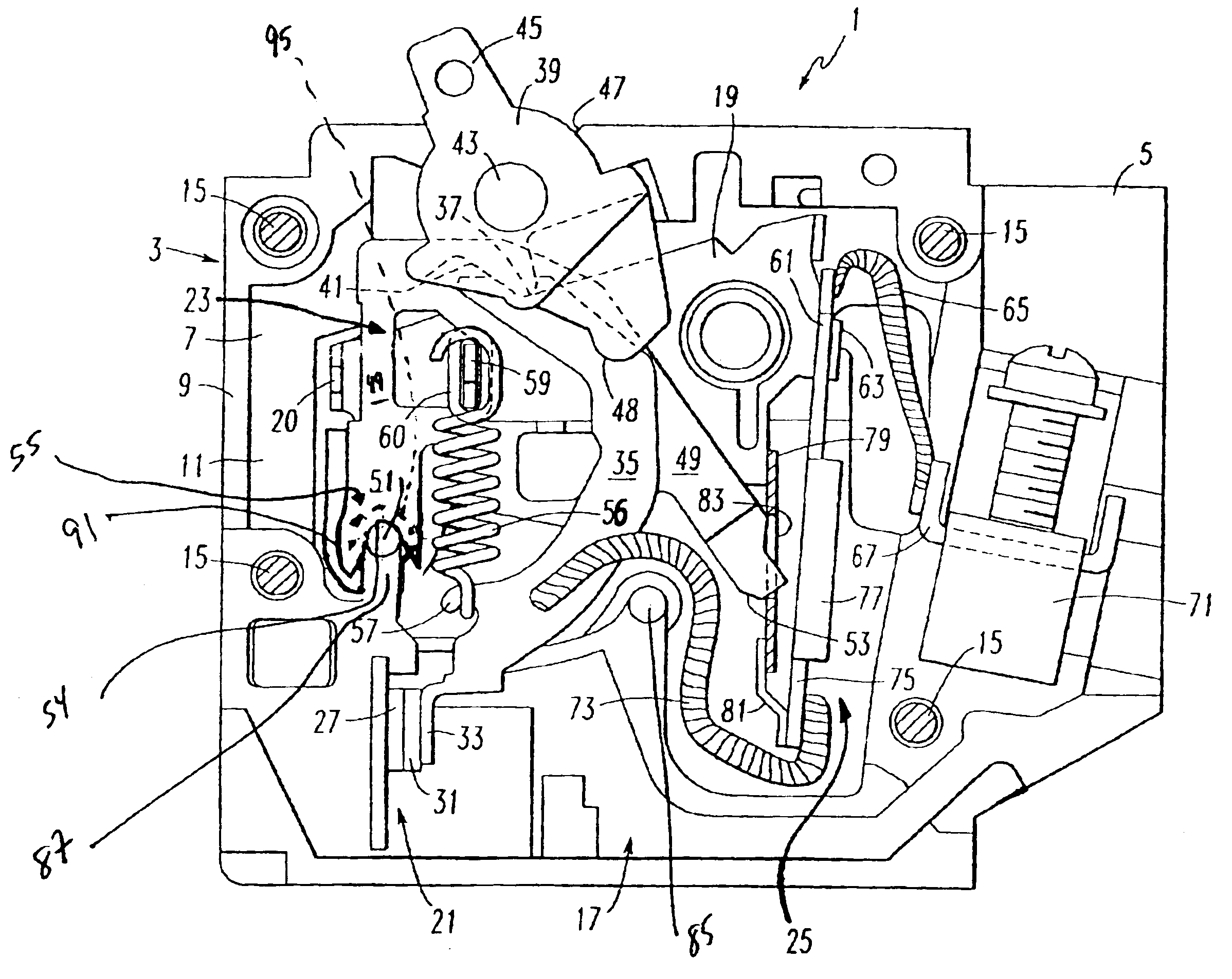
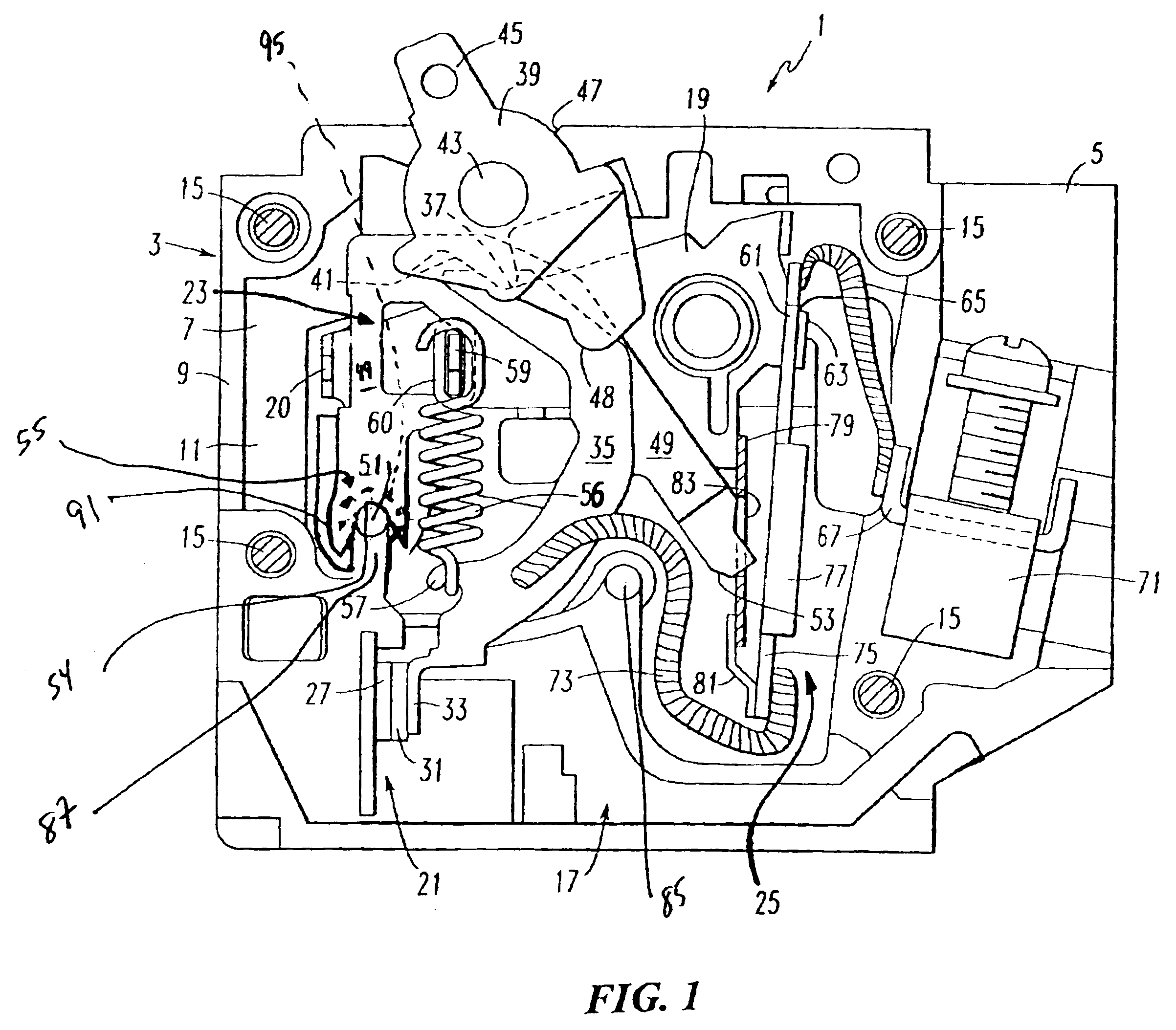
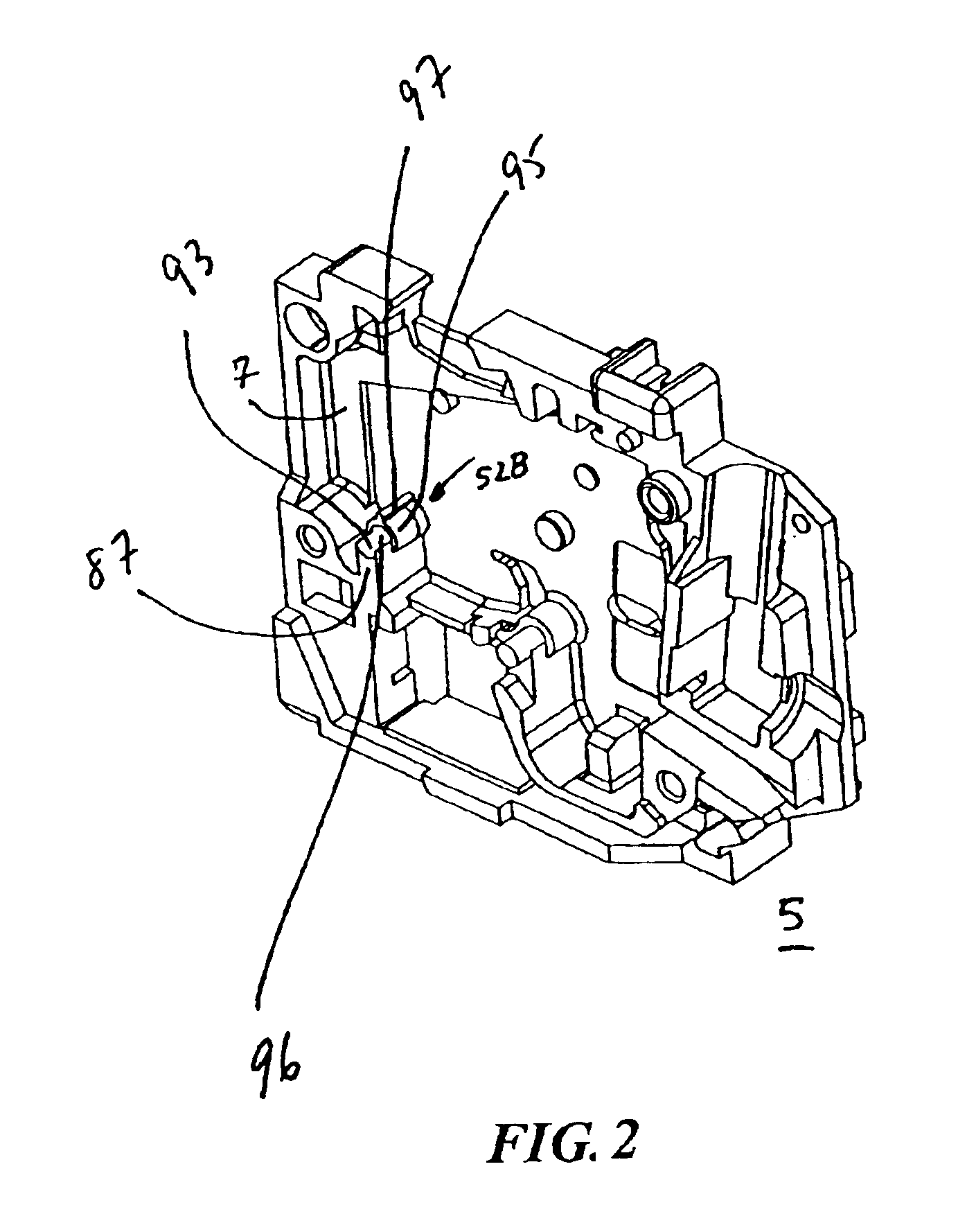
[0014]These needs and others are met by the present invention, which disposes a steel pivot pin in a recess of a molded housing of a circuit breaker. The steel pivot pin forms a pivot point for a cradle of the circuit breaker operating mechanism, thereby allowing the cradle to reliably rotate about the steel pivot pin and function through the operating requirements of the circuit breaker.

Problems solved by technology

However, whenever the circuit breaker housing is made from a stronger, albeit softer, material, the motion of the cradle wears into the molded pivot pin.
Hence, the cradle and, thus, its position with respect to the trip mechanism changes, thereby impacting operation of the circuit breaker.

Method used


Image

  • Circuit breaker including a cradle and a pivot pin therefor
  • Circuit breaker including a cradle and a pivot pin therefor
  • Circuit breaker including a cradle and a pivot pin therefor

Examples


Embodiment Construction

[0031]The present invention is disclosed in connection with a single pole, molded case, thermal / magnetic circuit breaker. However, it will be appreciated that the invention is applicable to a wide range of electrical switching apparatus, such as, for example, circuit breakers including a cradle, one or more poles, and a wide range of operating and / or trip mechanisms and housings. An example of a single pole, molded case, thermal / magnetic circuit breaker is disclosed in U.S. Pat. No. 5,805,038, which is incorporated by reference herein.

[0032]As employed herein, the terms “general U-shape” and “generally U-shaped” shall expressly include, but not be limited to, U-shapes and variations thereof, such as, for example, an arcuate portion or substantially arcuate portion attached on each end thereof to a leg portion, such as a linear, arcuate, substantially linear and / or substantially arcuate portion; a semi-circular portion or substantially semi-circular portion attached on each end there...


PUM


Abstract

A circuit breaker includes a molded housing having a base and a cover forming a recess. A cylindrical steel pivot pin is disposed in the recess of the housing. Fixed and movable separable contacts are disposed within the molded housing. An operating mechanism is disposed within the molded housing for moving the separable contacts between an open position and a closed position. The operating mechanism includes a cradle having a latch portion and a generally U-shaped pivot portion which pivotally engages the cylindrical steel pivot pin. A trip mechanism cooperates with the operating mechanism to trip open the separable contacts. The trip mechanism includes a portion which engages the latch portion of the cradle when the separable contacts are in the closed position.

Description

BACKGROUND OF THE INVENTION[0001]1. Field of the Invention[0002]The present invention relates generally to electrical switching apparatus and, more particularly, to circuit breakers including an operating mechanism having a pivoting cradle.[0003]2. Background Information[0004]Circuit breakers of the type having an operating mechanism and a trip mechanism, such as a thermal trip assembly and / or a magnetic trip assembly, which are automatically releasable to effect trip operations and manually resettable following trip operations are common and generally well known in the art. Examples of such circuit breakers are disclosed in U.S. Pat. Nos. 3,849,747; 4,933,653; and 5,008,645.[0005]Such circuit breakers, commonly referred to as “miniature” circuit breakers, have been in use for many years and their design has been refined to provide an effective, reliable circuit breaker, which can be easily and economically manufactured on a large scale. In addition, circuit breakers of this type ma...

Claims


Application Information

Patent Timeline
Patent Type & Authority Patents(United States)
IPC IPC(8): H01H71/10H01H71/52
CPCH01H71/524H01H2003/326
Inventor FELLO, JOSEPH P.BORONA, RUSSELL T.
Owner EATON INTELLIGENT POWER LTD
Learn More