
Systems and methods for classifying vehicles

a technology for classification and vehicles, applied in the field of vehicles toll collections, can solve problems such as extensive renovation of mechanical systems

Inactive Publication Date: 2005-05-17
THE REVENUE MARKETAB
View PDF23 Cites 42 Cited by
  • Summary
  • Abstract
  • Description
  • Claims
  • Application Information

AI Technical Summary

Benefits of technology

"The present invention provides a system for classifying vehicles using a capacitive sensor. The system includes a capacitance detector that can determine the weight of the vehicle based on the weight of the tires. The system can also classify the vehicle based on its tire width. The invention can be used in various applications such as weighing vehicles at a weighing station or identifying vehicles on a road."

Problems solved by technology

However, some of these mechanisms require extensive renovations and / or road construction at such toll plazas for their installation.

Method used


Image

  • Systems and methods for classifying vehicles
  • Systems and methods for classifying vehicles
  • Systems and methods for classifying vehicles

Examples


Embodiment Construction

[0029]In accordance with the principles of the present invention, systems and methods for vehicle classification are provided.

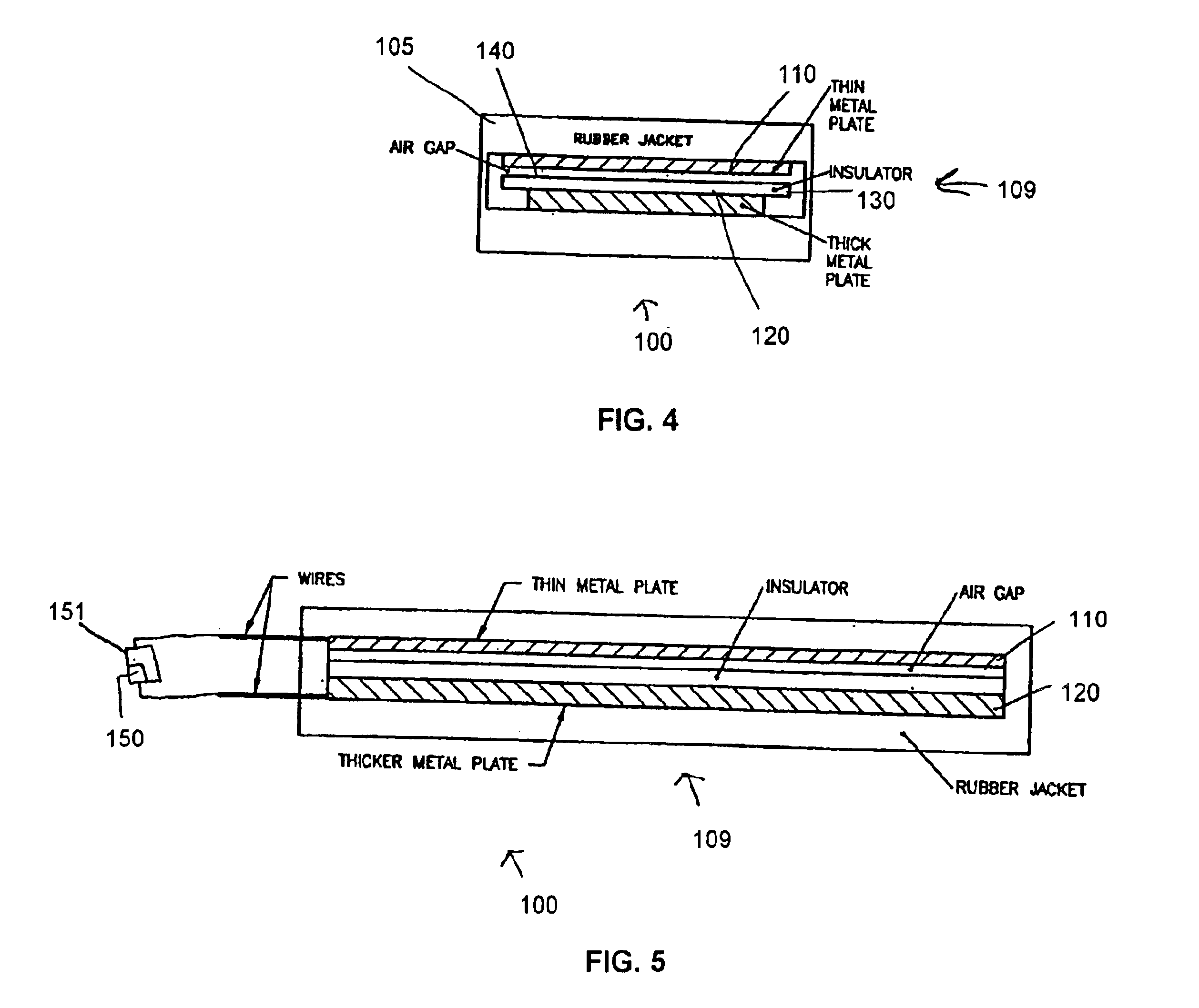
[0030]In an exemplary embodiment depicted in FIGS. 4-5, a system 100 for classifying a vehicle is provided which includes a capacitive sensor 109 and a capacitance detector 150. Capacitive sensor 109 is mounted in a rubber jacket 105 of a treadle (not shown) dimensioned to be located in a cavity (not shown) of a roadbed (not shown). Capacitive sensor 109 includes a first conductive strip 110 separated from a second conductive strip 120 by an electrical insulator 130 or dielectric. There also may be a space or air gap 140 between insulator 130 and first conductive strip 110. First conductive strip 110 and second conductive strip 120 may be electrically coupled to capacitance detector 150.

[0031]Capacitance detector 150 may be adapted to detect a capacitance between first conductive strip 110 and second conductive strip 120. In one example, capacitance detector ...


PUM


Abstract

A system for use in classifying a vehicle includes a capacitive sensor for operatively receiving a weight of a vehicle and a capacitance detector coupled to said capacitive sensor. The capacitance detector is adapted to determine a capacitance signal of the capacitive sensor in response to the capacitive sensor operatively receiving the weight of the vehicle.

Description

TECHNICAL FIELD[0001]This invention relates, in general, to toll collections for vehicles and, in particular, to systems and methods for use in classifying vehicles for toll collection purposes.BACKGROUND ART[0002]Tolls charged for the use of automobile toll highways may vary according to certain factors, such as vehicle weight and a number of axles per vehicle, for example. Because tolls vary based on such factors, it is necessary to obtain information about vehicles as they pass through toll plazas to ensure that proper fares are charged.[0003]Currently, a number of axles of vehicles moving through toll plazas may be determined through one or more sets of electrical contact switches located in one or more treadles located in the path of oncoming traffic as they pass through these plazas. Such treadles are typically arranged such that their longitudinal dimensions are substantially orthogonal to a direction of traffic. Also, treadles may be located in a cavity of a roadbed such tha...

Claims


Application Information

Patent Timeline
Patent Type & Authority Patents(United States)
IPC IPC(8): G01R27/26G04G9/00G07B15/06
CPCG07B15/00
Inventor DINGWALL, ROBERTMILNICK, PAULEMERICK, JOHNJAMEISON, GERALD
Owner THE REVENUE MARKETAB
Learn More