
Ergonomic swim fin apparatus

a fin and ergonomic technology, applied in the field of swim fins, can solve the problems of flat stiff paddle, uncomfortable use, pressure points on the top of the user's foot, etc., and achieve the effect of creating additional li

Inactive Publication Date: 2005-05-17
MELIUS JOHN DAVID
View PDF4 Cites 11 Cited by
  • Summary
  • Abstract
  • Description
  • Claims
  • Application Information

AI Technical Summary

Benefits of technology

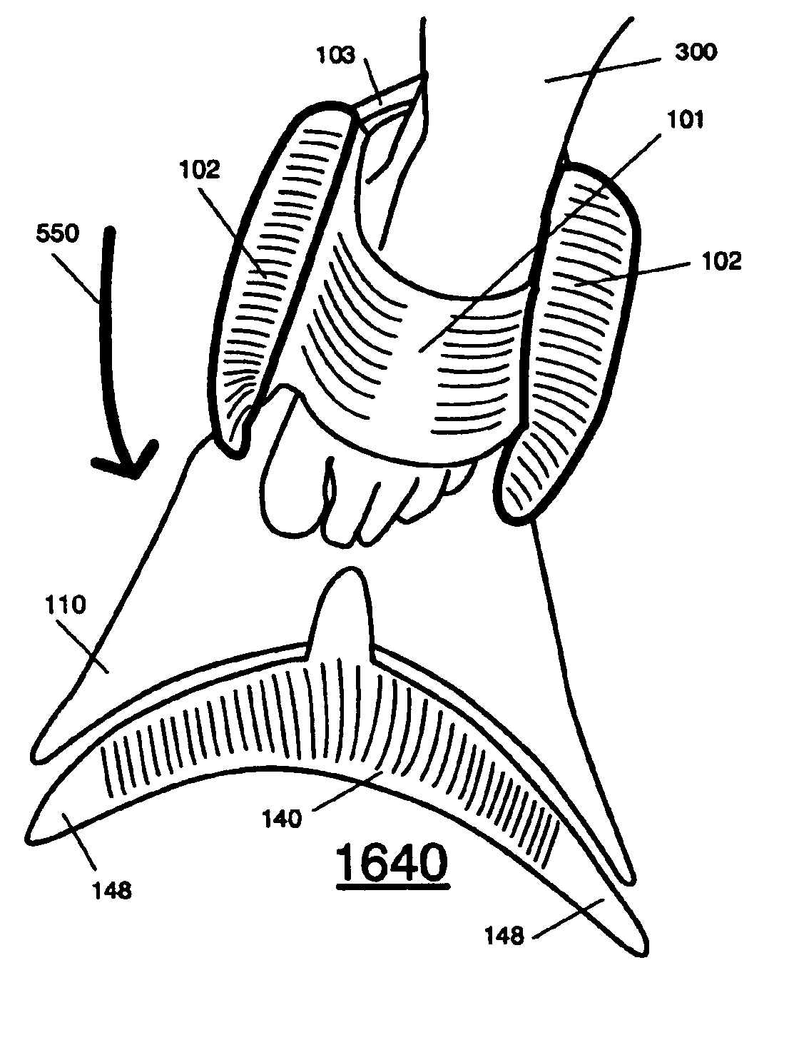
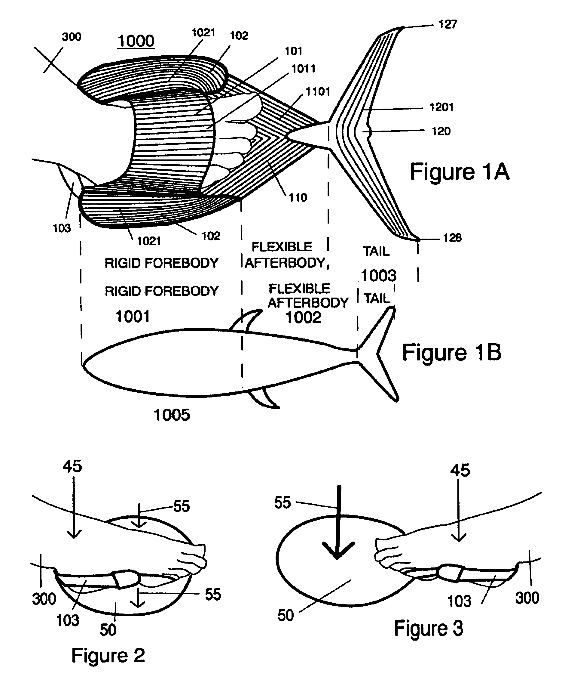
[0026]Channeling scoops are located between the flexible joints of the foot (the ankle and toes), and allow the swimmer substantially freer movement, and improve the ease of walking while wearing the swim fin apparatus disclosed herein. The channeling scoops can be used with traditional swim fin forms, and are preferably rounded to channel the water displaced by the user's foot. The present invention is easier and more efficient to use without any loss in propulsion even though the overall length of the swim fin can be substantially shortened. The use of the channeling scoops enable the capturing of energy used to move the foot through the water (which usually slides off the sides of the foot.)
[0027]The present invention also utilizes a flexible blade and symmetrical wing fin. The flexible blade and wing fin enhance and channel water flow from the flexible blade, and channel the flow of water further, while creating lift with the wing-like tail fin.
[0028]This invention results from the realization that a truly effective swim fin apparatus is a highly efficient form of propulsion for a human while swimming underwater or near the surface of the water. This can be achieved with a semi-rigid foot pocket or specially adapted shoe employing channeling scoops that convert the flow of water across the foot into a propulsion stroke, while allowing the foot the freedom to flex naturally at the ankle and toe joints.
[0029]The foot pocket is preferably connected to a flexible blade, which is configured to shape and channel the water across a symmetrical wing-shaped tail fin to provide additional propulsion through lift. The channeling scoops impel the foot to an optimum position during swimming and are preferably removable to selectively increase or decrease the speed and work output of the swimmer.
[0031]It is also an object of this invention to provide channeling scoops on each side of a user's foot to increase propulsion.
[0033]It is yet another object of this invention to channel water flow from the flexible blade to a symmetrical wing fin, to create additional lift.

Problems solved by technology

At best, the tail fin in this system acts like a webbed foot, with its associated problems.
U.S. Pat. No. 2,099,973 comes close to adapting the propulsion system of efficient fish type propulsion, but has several inherent problems.
This would be uncomfortable to use when swimming or walking, because the toes would continually be constricted and under substantial pressure.
Second, the lack of a formed foot pocket would cause pressure points on of the top of the user's foot.
Third, the flat stiff paddle does nothing to enhance or channel the flow of water over the fin to enhance propulsion.
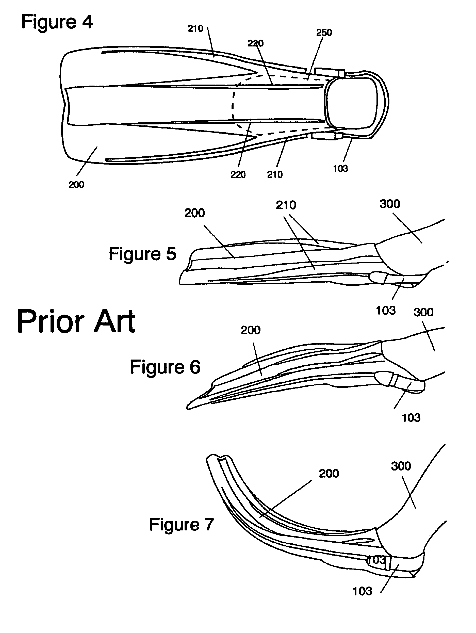
The invention described in U.S. Pat. No. 6,375,531 uses a stiff blade that extends beyond the toes which creates unnecessary work and undue pressures on the foot of the swimmer, and makes walking in the fins very difficult.
Webbed feet and paddles work to push water, but not as efficiently as the propulsion system used by fish.
Two clear problems with webbed feet and paddles are that water isn't pushed effectively, and a recovery stroke is required to arrive at a position to properly push on each stroke of the swim fins (a substantial waste of energy and a cause of drag.)

Method used


Image

  • Ergonomic swim fin apparatus
  • Ergonomic swim fin apparatus
  • Ergonomic swim fin apparatus

Examples


embodiment 2000

[0085]FIG. 12 illustrates an embodiment 2000 of the swim fin apparatus that has many of the traits of the swimming sandal / shoe / short swim fin apparatus 1400 found in FIG. 9. The swim fin apparatus 2000 contains a foot-pocket 101, opposing channeling scoops 102 located on opposite sides of the foot-pocket 101, the flexible blade sole 108, and at least one securing strap 103.

[0086]In this embodiment, the symmetrical flexible blade sole 108 is detachable from the flexible blade 110, and may be selectively attached and removed, for ease of shipping and handling. By providing a releasable attachment means such as a hook 1112 and catch 1111 at the toe end of the flexible blade sole 108, the distal end of the flexible blade 110 is removable, enabling the user to easily walk on land, without removing the entire swim fin apparatus.

[0087]The releasable attachment means such as a hook 1112 and catch 1111 preferably comprises a complimentary hook 1112 and catch 1111 means. In the embodiment sho...

embodiment 1500

[0099]FIG. 18 and FIG. 20 show different perspective views of a swim fin sandal apparatus 1500. The swim fin sandal apparatus 1500 is made of any appropriate waterproof material used in manufacturing sandals or swim fins. The material selected must be strong enough to support the weight of a user, and the pressures exerted by the channeling scoops 102 during swimming. In this embodiment 1500, the bottom instep strap 1014 and top instep strap 1015 preferably have a system of hooks and loops type fasteners 1017 attached to the bottom instep strap 1014 and to the top instep strap 1015, so that the hooks and loops type fasteners 1017 provide releasable and adjustable securement when the top instep strap 1015 and the bottom instep strap 1014 are engaged.

[0100]The instep strap loop 1018 will hold the two sides of the swim fin sandal apparatus 1500 together at the instep when the top instep strap 1015 is secured to the bottom instep strap 1014. Any known securement means may be used. In FI...

embodiment 120

[0111]Each tail fin apparatus shown in FIG. 22 and FIG. 23 has a connecting point 125 and a securement means 145 respectively located along the longitudinal central axis of the swim fin apparatus 1000. The connecting point 125 or a securement means 145 can be a permanent attachment, a continuation of the flexible blade 110, or a releasable connecting means, 118, and 1181. In FIG. 22, the tail fin 120 has a leading edge 124 and a trailing edge 121 that extend in substantially straight lines across the tail fin 120. To decrease the drag created by vortices produced by moving through water, the tail fin edge 129 located at the distal sides of the tail fin 120, has a lifting surface that creates lift and channels the water towards the center of the tail fin 120. This pulls water away from the edge, and thus decreases the moving water that can be created as vortices and drag on the outer sides of the tail fin 120. The tip 148 of the tail fin edge 129 decreases in size and tapers to a poi...


PUM


Abstract

The ergonomic swim fin apparatus comprises a foot-pocket sized to fit about a user's foot, channeling scoops are positioned on opposite sides of the footpocket, and a flexible blade extends from the foot-pocket to a trailing edge. A “wing shaped” tail fin is secured to the trailing edge of the flexible blade. The channeling scoops are rounded to channel the water displaced by the user's foot over the flexible blade and tail fin. The flexible blade and wing like tail fin channel water while enhancing lift and thrust. At least one securing strap is used to secure the user's foot to the foot-pocket. The tail fin is preferably selectively attachable and removable from the distal end of the flexible blade. The flow of water across the foot is converted by the channeling scoops into a propulsion stroke in both the up and down strokes, while allowing the foot the freedom to flex naturally at the ankle and toe joints.

Description

CROSS REFERENCE TO RELATED APPLICATIONS[0001]This utility patent application claims priority of provisional patent Application 60 / 265,581 filed Feb. 2, 2001, which is incorporated by reference herein.TECHNICAL FIELD[0002]This disclosure relates to swim fins used for swimming underwater or at the surface, or as swim fins that can be worn with adapted footwear.BACKGROUND OF THE INVENTION[0003]This invention relates generally to the field of swimming and diving, and more particularly to an ergonomic swim fin apparatus based on the locomotion methods and strategies used by the most efficient fish. This invention can be assembled to various levels of complexity, to be used to swim at varying degrees of effectiveness and purpose. Much work has been done in recent years in biomimetics to study efficient swimming fish to try to effect a man-made free moving aquatic device that- approaches their propulsion, efficiency, acceleration and maneuverability. Universities such as MIT, Northeastern ...

Claims


Application Information

Patent Timeline
Patent Type & Authority Patents(United States)
IPC IPC(8): A63B31/11
CPCA63B31/11
Inventor MELIUS, JOHN DAVID
Owner MELIUS JOHN DAVID
Learn More