
High G oxygen mask for aircrew

a mask and oxygen technology, applied in the field of oxygen masks, can solve the problems of automatic changes in pressure in the interior of the mask, masks are very uncomfortable to wear,

Inactive Publication Date: 2005-05-17
GRIFFITHS JOSEPH ANTHONY
View PDF13 Cites 23 Cited by
  • Summary
  • Abstract
  • Description
  • Claims
  • Application Information

AI Technical Summary

Benefits of technology

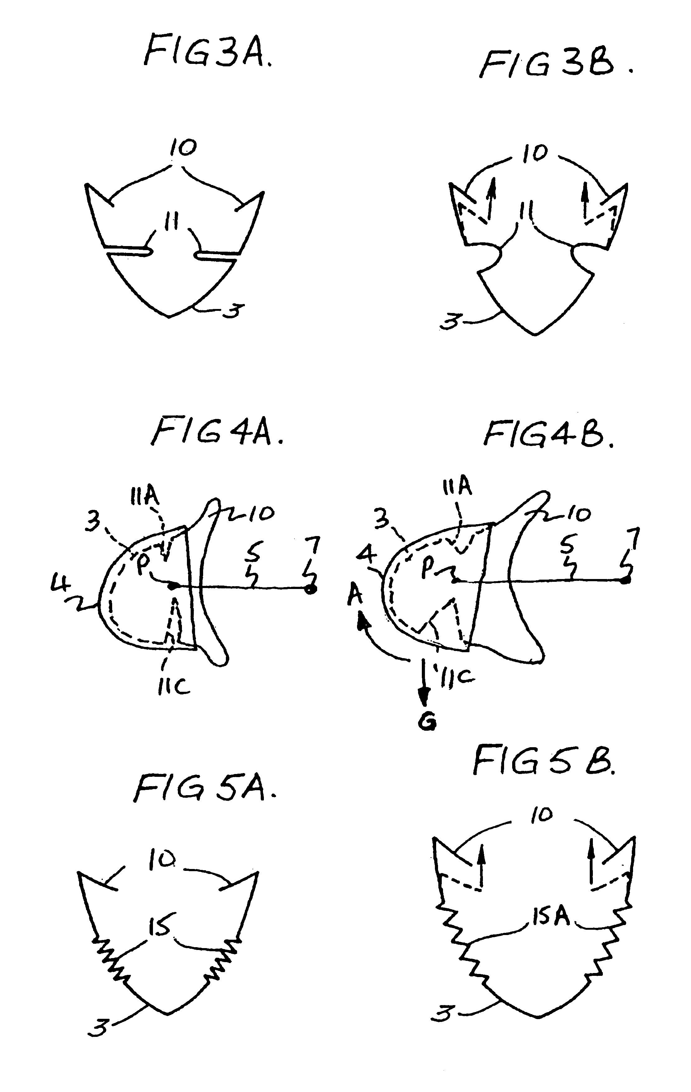
[0017]In some embodiments, the flexible oro-nasal mask comprises a plurality of annular inwardly directed recesses formed in the a wall of the oro-nasal mask to provide a bellows therein. In other embodiments, a wall of the oro-nasal mask includes a convoluted rolling section, a thickness of the oro-nasal mask wall in a region of the convoluted rolling section being less than a thickness of a remainder of the mask thereby allowing the mask to be rolled back on itself into an S-shaped configuration. In some embodiments, the breathing apparatus further comprises an attachment to maintain the mask a fixed distance from the helmet.

Problems solved by technology

Thus, changes in the G-forces applied to the regulator controlling the breathable gas supply result in automatic changes in pressure in the interior of the mask.
Indeed, he has to do this because the pressure exerted on his face when the toggle is engaged is so great that the mask is very uncomfortable to wear.
The main problem with this arrangement is that the pilot must remember to engage the toggle before he makes a turn (possibly difficult in a combat situation) and release it after the turn has been completed as the pressure on his face is too high to be comfortable for normal flying.

Method used


Image

  • High G oxygen mask for aircrew
  • High G oxygen mask for aircrew
  • High G oxygen mask for aircrew

Examples


Embodiment Construction

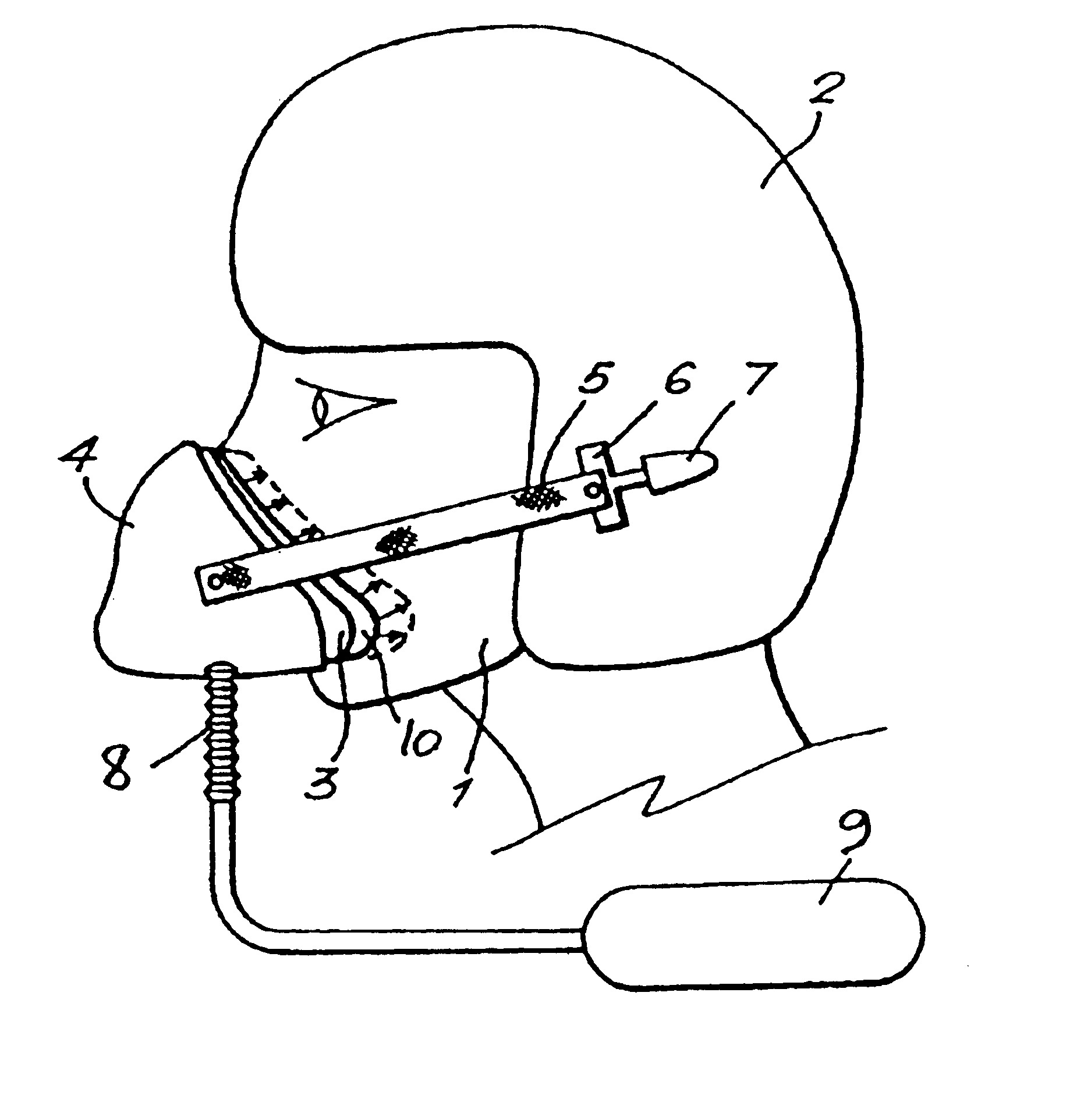
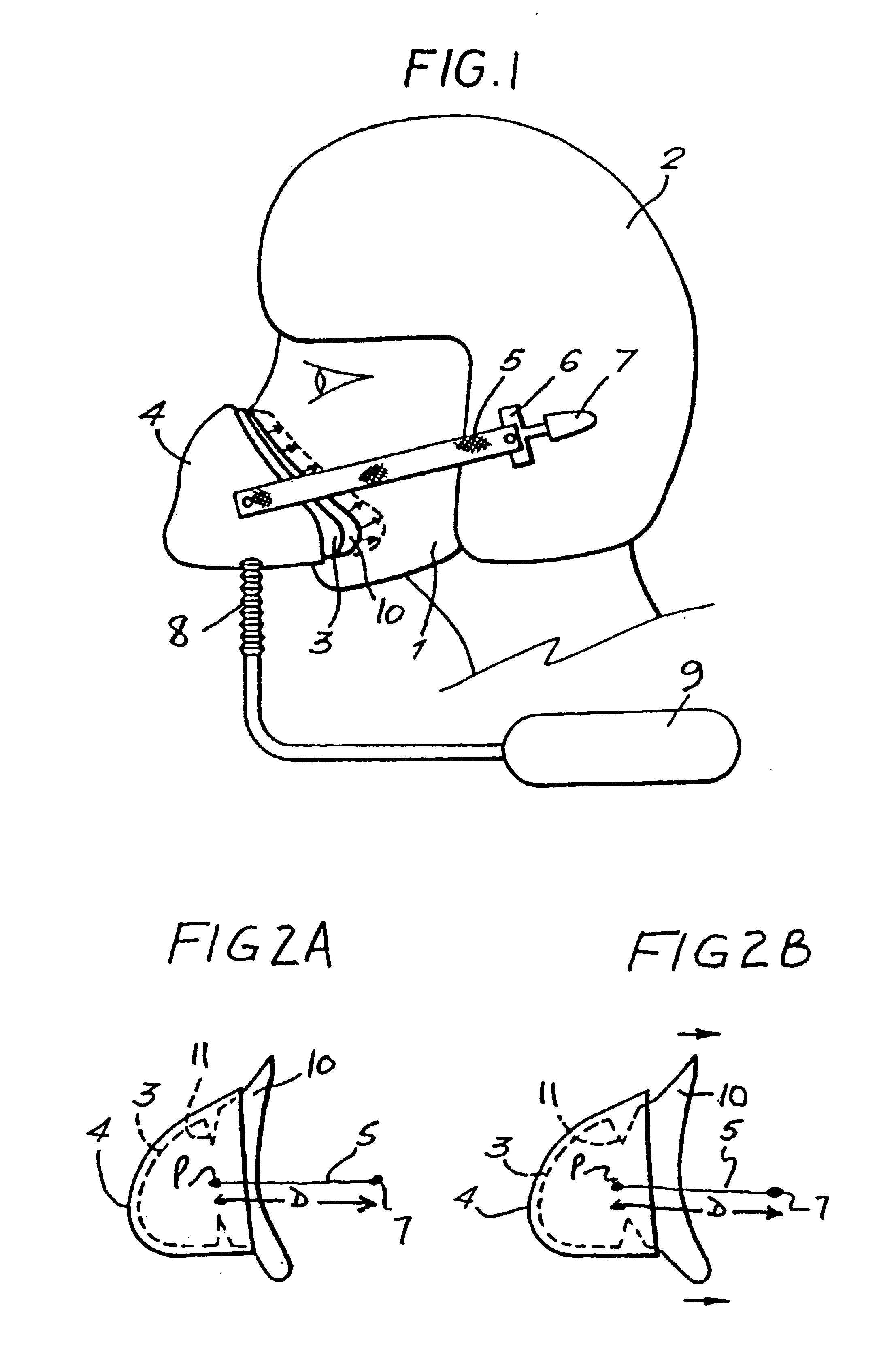
[0031]Referring now to the drawings, FIG. 1 shows a pilot 1 wearing a rigid protective helmet 2. A flexible oro-nasal mask 3, usually made of a natural synthetic rubber, surrounds the pilot's nose and mouth and is mounted in a rigid plastics shell 4 attached to the helmet 2 by means of harness arrangement 5 which includes adjustable means (not shown) so that'its length can be readily altered to ensure that the oro-nasal mask 3 rests comfortably on the pilot's face with its peripheral edge 10 making a proper seal with the area of the pilot's face surrounding his nose and mouth. It should be noted that the harness 5 is made of an in extensible material such as webbing or a metal wire mounted at mounting point P to the rigid shell 4 and at its opposite end in mounting 7 so that when the shell 4 and mask 3 are in position on the pilot's face, the position of the shell 4 relative to the helmet 2 cannot change and it remains at a fixed distance D therefrom (see FIGS. 2A and 2B).

[0032]A br...


PUM


Abstract

A flexible oro-nasal mask for mounting in a rigid shell attached to the helmet of aircrew at a fixed distance therefrom. The flexible oro-nasal mask incorporates an inspiratory and expiratory valve and the periphery of the mask is adapted to make a seal with the pilot's face. The oro-nasal mask includes an extendable structure which presses the periphery of the mask automatically towards the pilot's face to improve the seal therewith when gas at a pressure above that required for normal breathing is supplied to the mask. The extendable structure is configured so that when gas at a high pressure is supplied to the interior of the mask, the portion in the bottom region of the mask extends more than the portion in the upper region of the mask and the bottom of the mask is moved away from the wearer's face by a greater amount in the chin region than the nose region and the mask pivots upwardly automatically to compensate for the effects of G thereon. One embodiment of an extendable structure comprises an annular inwardly directed re-entrant recess formed in the wall of the mask adjacent the peripheral seal, the depth of said recess in the bottom half of the mask being greater than the depth in the top half thereof.

Description

RELATED APPLICATIONS[0001]Foreign priority benefits are claimed under 35 U.S.C. §119(a) of United Kingdom application number 0221687.7, filed Sep. 18, 2002 and titled “High G Oxygen Mask for Air crew.”BACKGROUND OF INVENTION[0002]1. Field of Invention[0003]This invention relates to an oxygen mask for use by pilot's, and more particularly to an oxygen mask for use by pilot's who are subjected to high G forces.[0004]2. Discussion of Related Art[0005]Breathing equipment for air crew normally comprises a flexible face mask having an inspiratory valve supplied with oxygen or some other breathable gas and an expiratory valve to allow the pilot to expel the air from the mask on exhalation. The face mask is attached to the pilot's flying helmet by means of a harness incorporating a releasable fitting.[0006]In fighter aircraft, it is essential that the face mask makes a seal with the pilot's face at all times. Under normal flying conditions, this is not a problem as the pilot adjusts the har...

Claims


Application Information

Patent Timeline
Patent Type & Authority Patents(United States)
IPC IPC(8): A62B18/02A62B18/00A62B18/08
CPCA62B18/084A62B18/02
Inventor GRIFFITHS, JOSEPH ANTHONY
Owner GRIFFITHS JOSEPH ANTHONY
Learn More