
Image forming apparatus and convey control method for recycle toner

a technology of conveying control and toner, which is applied in the field of image forming apparatus, can solve the problems of hard mixing with the carrier, degrading electrostatic properties, and posing a problem, and achieve the effect of no degradation of image quality

Inactive Publication Date: 2005-05-10
KONICA CORP
View PDF5 Cites 5 Cited by
  • Summary
  • Abstract
  • Description
  • Claims
  • Application Information

AI Technical Summary

Benefits of technology

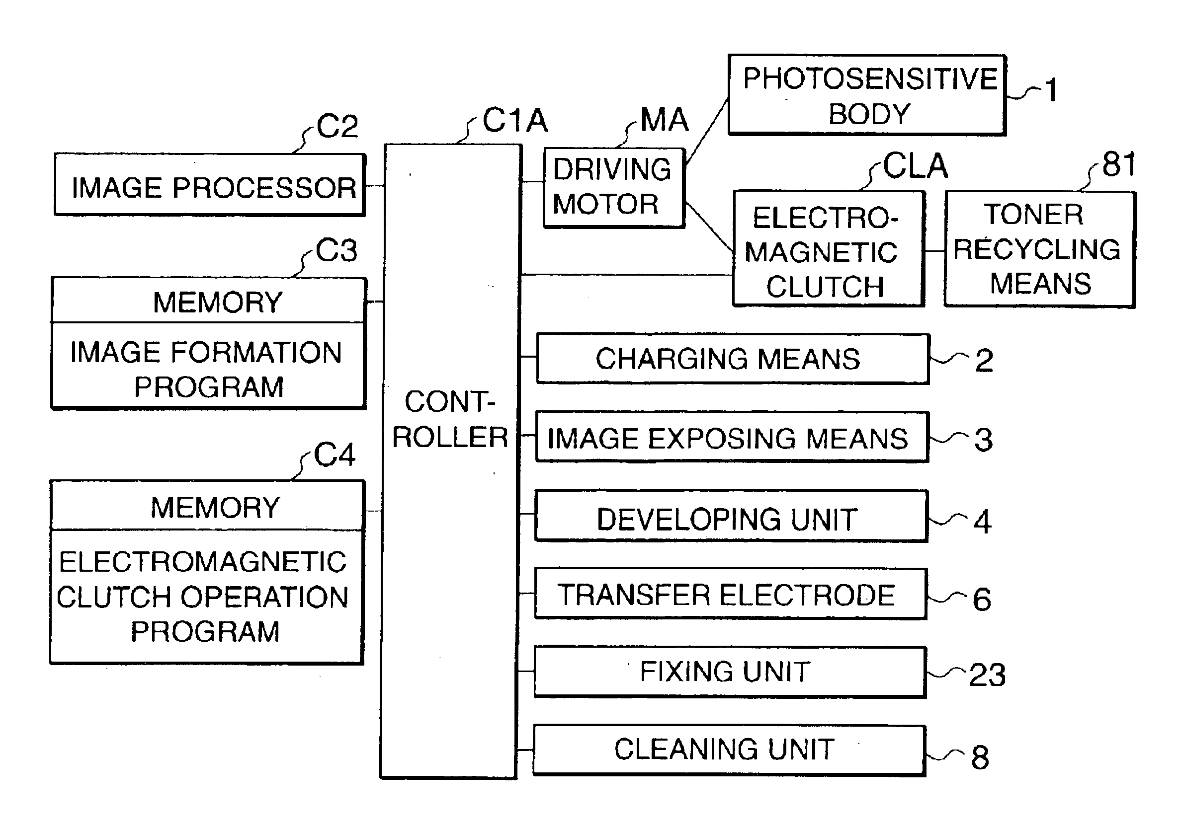
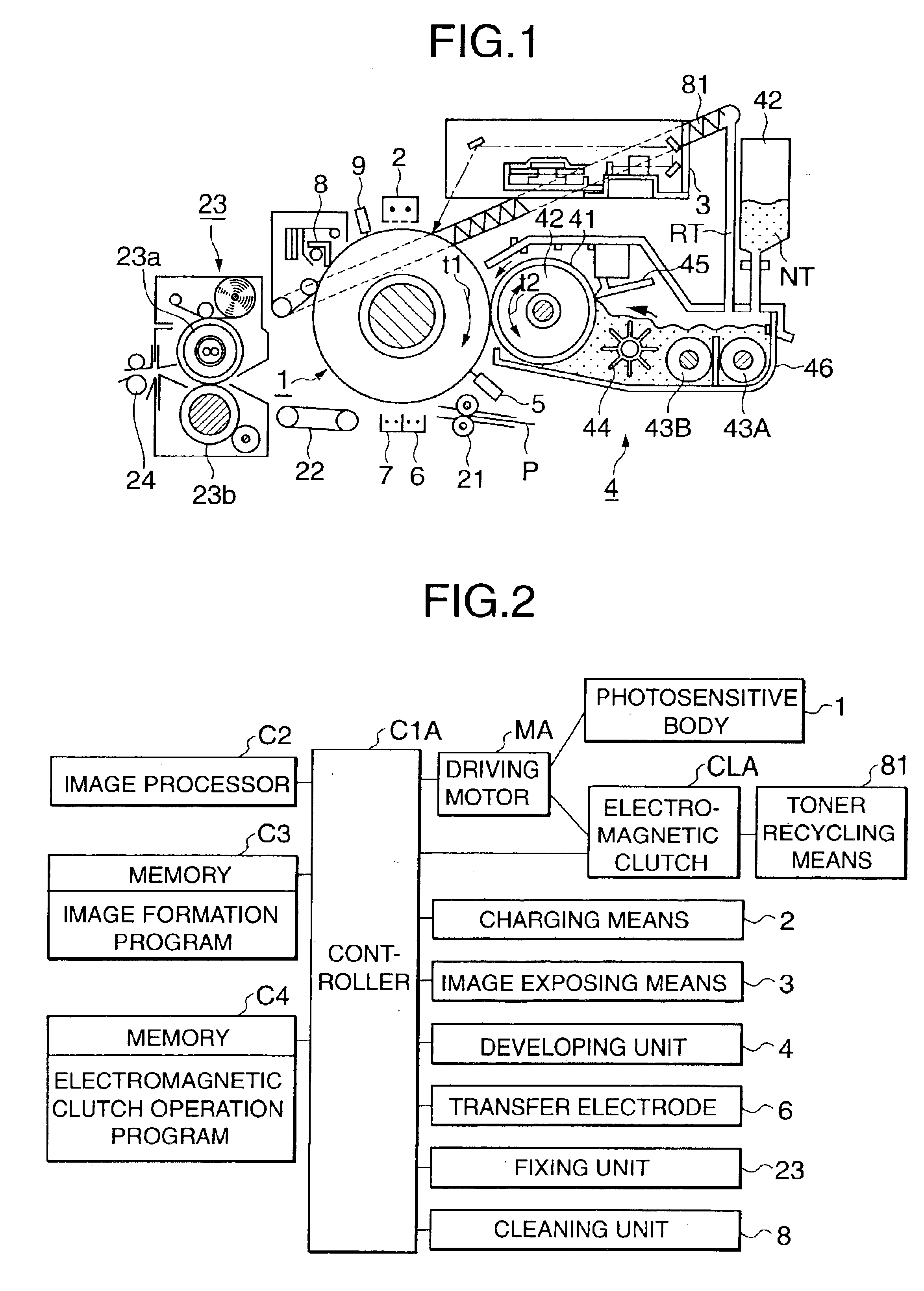
[0014]The present invention has been made in view of the above situation of the prior art, and has as its object to provide an image forming apparatus in which the supply amount of recycle toner can be controlled so that, while the recycling means shares one driving source with the latent image carrier or fixing unit, no degradation in image quality occurs even when, e.g., the printing ratio of the image formation pattern is low continuously or even in operation after long-time stop.
[0020]The recycling scheme is very excellent in that it does not dispose, as waste toner, toner which is not transferred but recovered, and reuses it. As is apparent from the above aspects, with the image forming apparatus of the present invention, the problem of how the recycling means should be driven and the problem of the phenomenon in which fogging or character thickening occurs during development due to the recycle toner containing damaged toner can be solved without sacrificing the cost or space, while an image with a high image quality can be maintained for a long period of time.

Problems solved by technology

When the recycle toner is compared to new toner, it has lower flowability, it is harder to mix with the carrier, and its electrostatic properties also degrade.
When the recycle toner is developed again, it tends to pose a problem such as fogging or character thickening.
Therefore, when the recycle toner described above is used, the above problem is obvious.
This problem of degradation in image quality occurs as follows.
This causes obvious degradation in image quality.
It is known that the problem of degradation in image quality tends to occur when the image forming apparatus has been kept stopped for a long period of time, e.g., for 2 h or more, and then several hundred prints are output.
This is because the charges of the recycle toner damaged due to the long-time stop are decreased.
If, however, a single driving source is provided to the recycling means in order to control the amount of recycle toner, cost reduction and space saving cannot be achieved.

Method used


Image

  • Image forming apparatus and convey control method for recycle toner
  • Image forming apparatus and convey control method for recycle toner
  • Image forming apparatus and convey control method for recycle toner

Examples


operation example 1

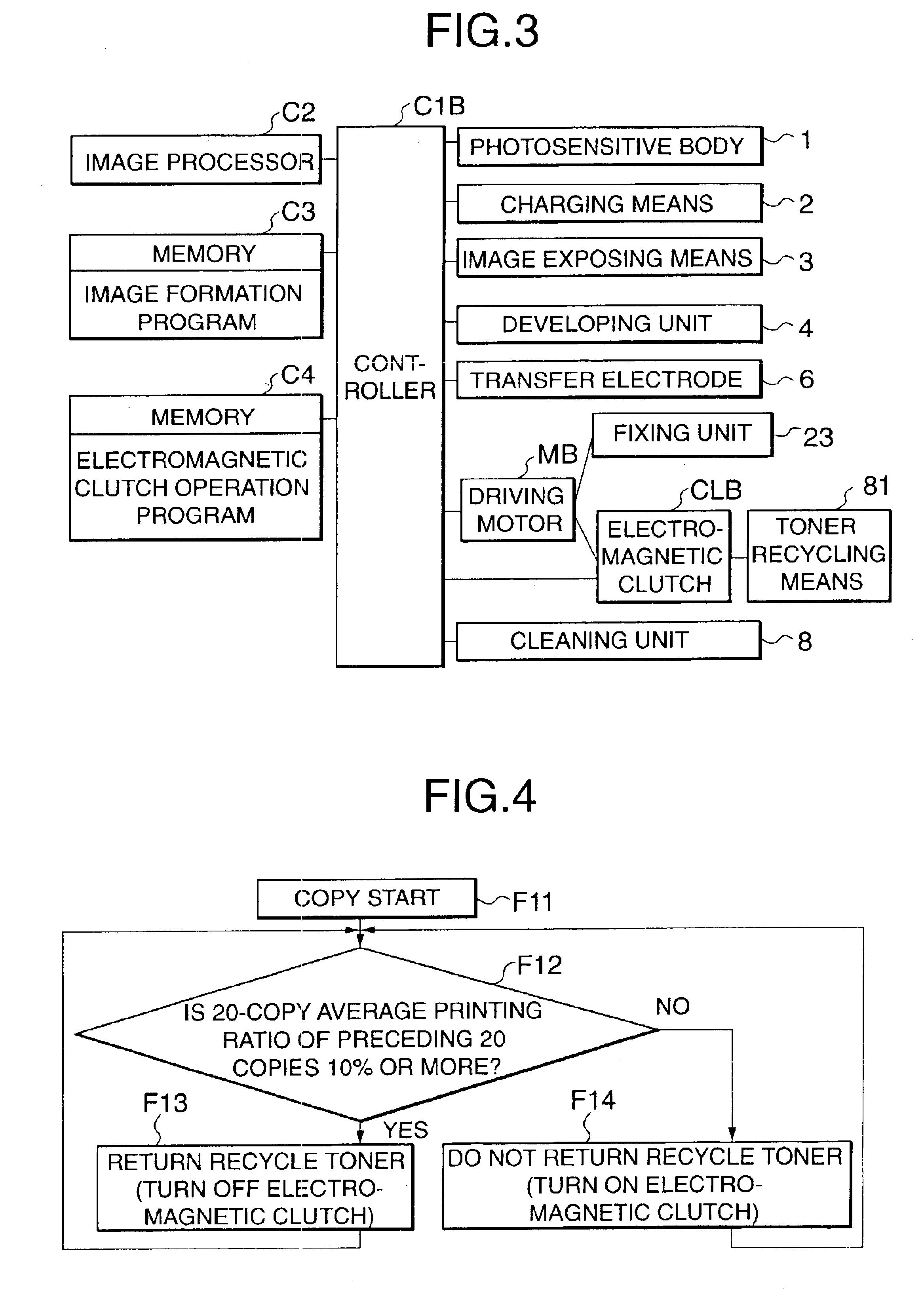
[0056]According to convey control for the recycle toner to be described in operation example 1, control operation is performed to suppress the return amount of the recycle toner when the printing ratio of the image pattern is low. FIG. 4 shows a flow chart of this control.

[0057]In an image processor C2, when image data is to be subjected to image processes such as tone correction, the printing ratio of an image pattern: per image is measured and is stored in the memory.

[0058]When copying is started (F11), the controller C1A (C1B) calculates a 20-copy average printing ratio of preceding 20 copies stored in the memory, and checks whether the obtained average printing ratio is 10% (as a low printing ratio) or more (F12).

[0059]If the average printing ratio of the 20 copies is 10% or more, the electromagnetic clutch CLA (CLB) maintains OFF, and transmits the driving force to return the recycle toner to the developing unit 4 (F13).

[0060]If the average printing ratio of the 20 copies is le...

operation example 2

[0062]In the flow of operation example 1, when the space in the cleaning unit 8 for storing the recovery toner recovered by the cleaning means is small, the recovery toner which is not conveyed but left may fill the cleaning unit 8 to overflow. Hence, when an image pattern with a high printing ratio with which a large amount of recovery toner may be produced is to be output, the electromagnetic clutch CLA (CLB) is controlled to perform recycling in combination with the flow of operation example 1. This is operation example 2. FIG. 5 shows a flow chart of this control.

[0063]In the image processor C2, when an image data process is to be performed, the printing ratio of an image pattern per image is measured and is stored in the memory.

[0064]When copying is started (F21), the controller C1A (C1B) calculates a 20-copy average printing ratio of preceding 20 copies stored in the memory, and checks whether the obtained printing ratio is 10% (as a low printing ratio) or more (F22).

[0065]If ...

operation example 3

[0070]When the image forming apparatus resumes operation after it has been stopped for a long period of time, an inconvenience such as fogging or character thickening tends to occur in the print image while several hundred copies are output. According to operation example 3, the amount of recycle toner to be returned to the developing unit 4 is controlled while the several hundred copies are output after the long-time stop. FIG. 6 shows a flow chart of this control.

[0071]The fixing unit 23 has a temperature sensor for measuring the temperature of the fixing unit 23. When the power supply is turned on (F31), the controller C1A (C1B) checks whether the fixing unit temperature detected by the temperature sensor is 50° C. or more (F32).

[0072]If the fixing unit temperature is 50° C. or more, that is, if the stop time since the last copy is output is not very long, the electromagnetic clutch CLA (CLB) is turned off to transmit the driving force, and the recycle toner is returned to the de...


PUM


Abstract

This invention relates to an image forming apparatus which employs a recycling scheme of recovering and reusing transfer residue toner, and a convey control method for recycle toner. In order to prevent a phenomenon such as fogging or character thickening, a toner recycle mechanism shares one driving source with a photosensitive body or fixing unit, and includes an electromagnetic clutch for switching driving force transmission to the recycling means when driving the photosensitive body or fixing unit, and a controller which controls power supply to the electromagnetic clutch. The convey control method for recycle toner includes the steps of starting copying, measuring a printing ratio of an image pattern per image, and suppressing a return amount of the recycle toner when the printing ratio of the image pattern is low.

Description

BACKGROUND OF THE INVENTION[0001]1. Field of the Invention[0002]The present invention relates to an image forming apparatus for development by using a two-component developing agent in accordance with electrophotography and, more particularly, to an image forming apparatus which employs a recycling scheme of recovering and reusing transfer residue toner and a convey control method for recycle toner.[0003]2. Description of the Related Art[0004]According to an example of an image forming process of forming an image by electrophotography, an electrostatic latent image is formed on a latent image carrier such as a photosensitive body. The formed electrostatic latent image is developed by a developing means to form a toner image on the latent image carrier. The formed toner image is transferred onto transfer paper by a transfer means. The transferred toner image is fixed on the transfer paper by a fixing means. Thus, an image is formed on the transfer paper. According to another example,...

Claims


Application Information

Patent Timeline
Patent Type & Authority Patents(United States)
IPC IPC(8): G03G21/10G03G21/14G03G15/00G03G15/08G03G15/20G03G21/00
CPCG03G21/105
Inventor TOKIMATSU, HIROYUKIOHTANI, JUNICHI
Owner KONICA CORP
Learn More