Measurement box with module for measuring wafer characteristics

a technology of measurement box and wafer, which is applied in the direction of instruments, coatings, material analysis, etc., can solve the problems of high cost and complex integration of measurement techniques in processing equipment, and achieve the effect of meaningful measurement of wafers, high integrity and compatibility

Inactive Publication Date: 2005-05-10
RUDOLPH TECH GERMANY
View PDF6 Cites 1 Cited by
  • Summary
  • Abstract
  • Description
  • Claims
  • Application Information

AI Technical Summary

Benefits of technology

[0012]The loading opening is used to deliver the wafers to the measuring device and to remove them again after measurement is completed. Since the pressure in the processing tool to which the measurement module is coupled is positive, air, due to the pressure difference, flows out of the processing tool through the loading opening into the measurement box. To ensure a continuous flow within the measurement box, a corresponding ventilation device is provided. The loading opening and the ventilation device are preferably adjusted to one another so as to ensure airflow within the measurement box. This prevents on the one hand impurities from penetrating into the measurement box from the outside and on the other hand eddies from forming within the measurement box, which might affect the measurement.
[0014]The base area of the enclosure is preferably ≦350 mm×≦400 mm. Since the dimensions of the measuring head are preferably less than 150·300 mm and the wafer is rotated during measurement while the measuring head is simultaneously displaced by means of a linear motion, the space required for measuring the wafer is so small that the base area of the measurement box can be limited to 350·400 mm or less. Thus, it is also excellently suited for use in wafer production plants in the locations where the load ports are provided. This has the advantage that no modifications need to be made in the wafer processing equipment, either on the processing tool or the EFEM. This achieves a high measure of integrity and compatibility.
[0018]The ventilation opening is preferably arranged in the enclosure wall opposite the loading opening. This facilitates the formation of a flow of air within the measurement box.

Problems solved by technology

The integration of measurement techniques in the processing equipment is often highly complex, as it frequently requires modifications in both systems, i.e. in the processing equipment and in the measurement system, which in turn is connected with additional costs.

Method used


Image

  • Measurement box with module for measuring wafer characteristics
  • Measurement box with module for measuring wafer characteristics
  • Measurement box with module for measuring wafer characteristics

Examples


Embodiment Construction

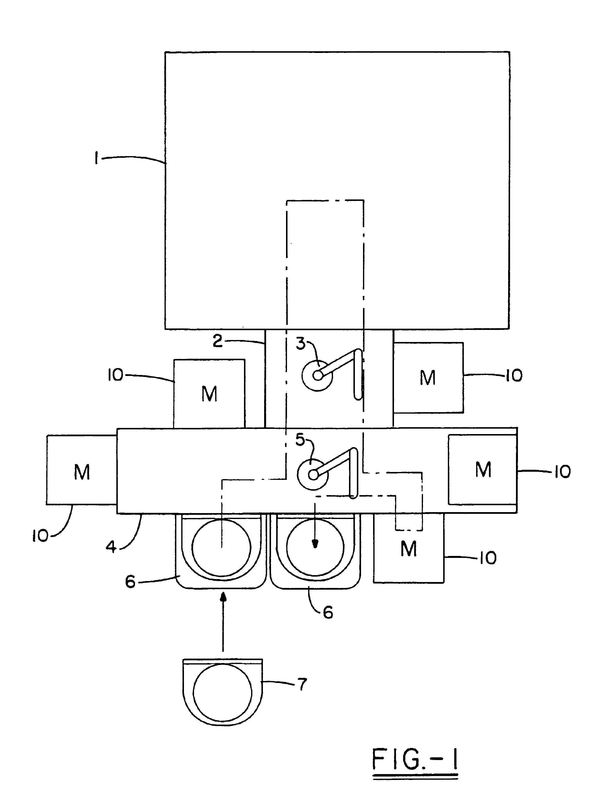
[0026]FIG. 1 schematically depicts a wafer processing unit. A vacuum lock with a lock robot 3 arranged therein is connected upstream from processing tool 1 in which the wafers are processed. Said lock robot 3 transports the wafers from an EFEM 4 into the processing tool 1. The EFEM is equipped with load ports 6 on which wafer containers 7 are positioned. Furthermore, an EFEM robot 5 is arranged in the EFEM. The measurement box 10 according to the invention can be arranged at different locations, which in FIG. 1 are identified as M. The measurement box 10 can, for instance, be arranged in vacuum lock 2 or on the sidewalls of EFEM 4, here particularly in the location of load ports 6. Due to its compact dimensions, which are smaller than those of load ports 6, measurement box 10 can be easily mounted wherever wafers need to be measured.

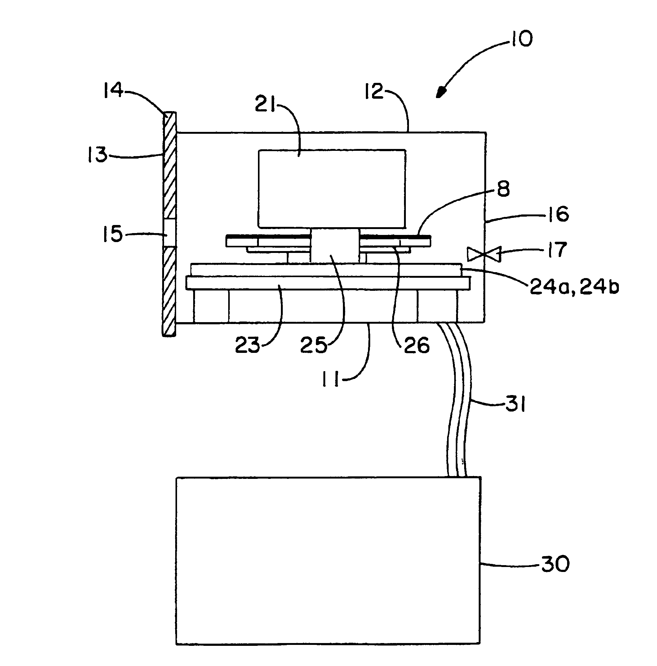
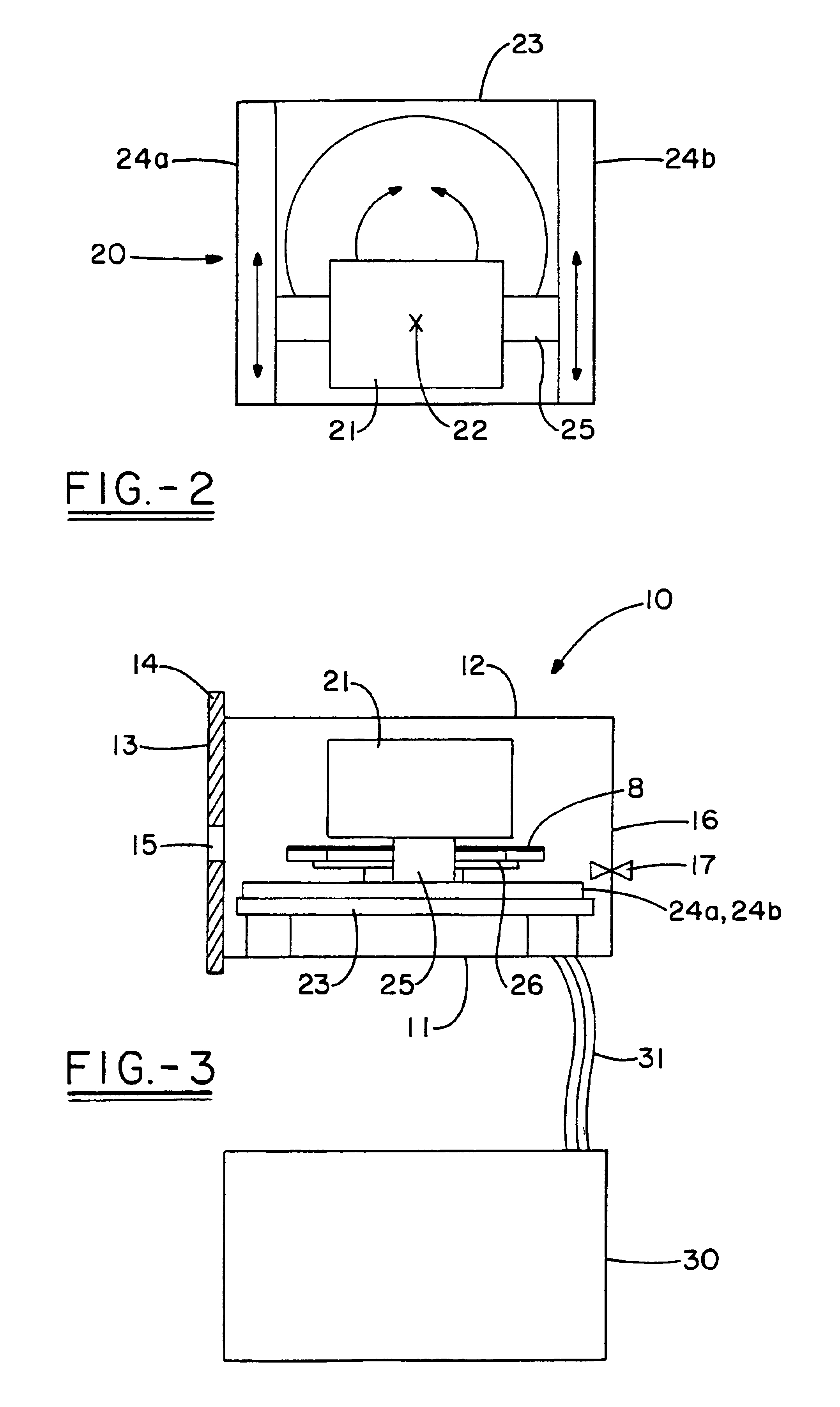
[0027]FIG. 2 is a top view onto a measurement module 20, which is arranged in measurement box 10. This measurement module 20 comprises a plane table 23 ...


PUM

PropertyMeasurementUnit
diameteraaaaaaaaaa
pressureaaaaaaaaaa
dimensionsaaaaaaaaaa

Abstract

A measurement box which can be integrated into existing wafer processing equipment. The measurement box comprises an enclosure which contains a measurement module for measuring objects such as the surfaces of wafers. The measurement module is equipped with a miniaturized measuring device and has a displaceable measuring head and a plane table with a rotatable wafer holder. The enclosure has at least one loading opening for the wafer to pass through as well as a ventilation device.

Description

FIELD OF THE INVENTION[0001]The invention relates to a measurement box for wafer processing equipment.BACKGROUND OF THE INVENTION[0002]For quality control in the manufacture of semiconductor chips, particularly the manufacture of wafers with a diameter of 300 mm, integrated measurement techniques are increasingly used. In integrated measurement techniques, unlike in conventional stand-alone methods, the measuring device is directly connected to, and integrated in, the production equipment. This is to ensure that quality control is as close as possible to the process.[0003]The integration of measurement techniques in the processing equipment is often highly complex, as it frequently requires modifications in both systems, i.e. in the processing equipment and in the measurement system, which in turn is connected with additional costs.[0004]In 300 mm wafer technology, however, a high degree of standardization is found. The processing equipment is provided with so-called Equipment Front...

Claims


Application Information

Patent Timeline
Patent Type & Authority Patents(United States)
IPC IPC(8): H01L21/00
CPCH01L21/67288H01L21/67253
Inventor ABRAHAM, MICHAEL
Owner RUDOLPH TECH GERMANY
Why Eureka
Try Eureka