
Driving waveform generator and method of generating driving waveform

a technology of driving waveform and generator, which is applied in the direction of pulse generator, pulse technique, instruments, etc., can solve the problems of unstable operation of the driving element and errors in each period, and achieve the effect of preventing accumulation of errors and preventing an abrupt change of the driving waveform

Inactive Publication Date: 2005-05-10
SEIKO EPSON CORP
View PDF10 Cites 7 Cited by
  • Summary
  • Abstract
  • Description
  • Claims
  • Application Information

AI Technical Summary

Benefits of technology

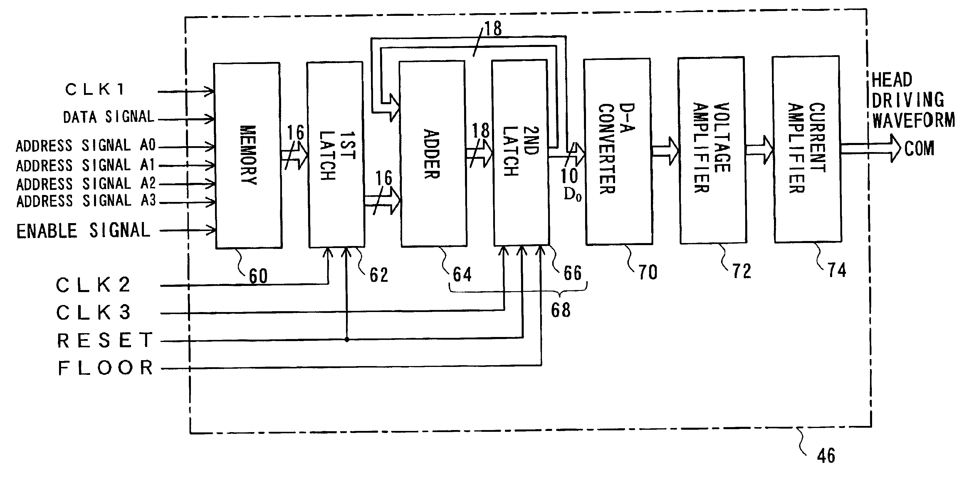
The present invention is about a technique to prevent errors in generating a driving waveform by calculation. It achieves this by summing up gradient data and carrying out digital-to-analog conversion with regards to specific upper columns in the result of summation. The technique corrects the result of summation to a predetermined value under a predetermined condition to cancel out potential effects of cumulative error. The correction is carried out by clearing residual lower columns in the result of summation other than the specific upper columns at a predetermined timing. The technique can be used in various applications such as printing apparatus, driving waveform generator, and method of generating a driving waveform.

Problems solved by technology

In the actual conditions, however, there is an error in each period.
The overflow or the underflow leads to an abrupt change of the driving waveform and undesirably makes the operation of the driving element unstable.

Method used


Image

  • Driving waveform generator and method of generating driving waveform
  • Driving waveform generator and method of generating driving waveform
  • Driving waveform generator and method of generating driving waveform

Examples


first embodiment

A. First Embodiment

A1. General Structure of Printing Apparatus

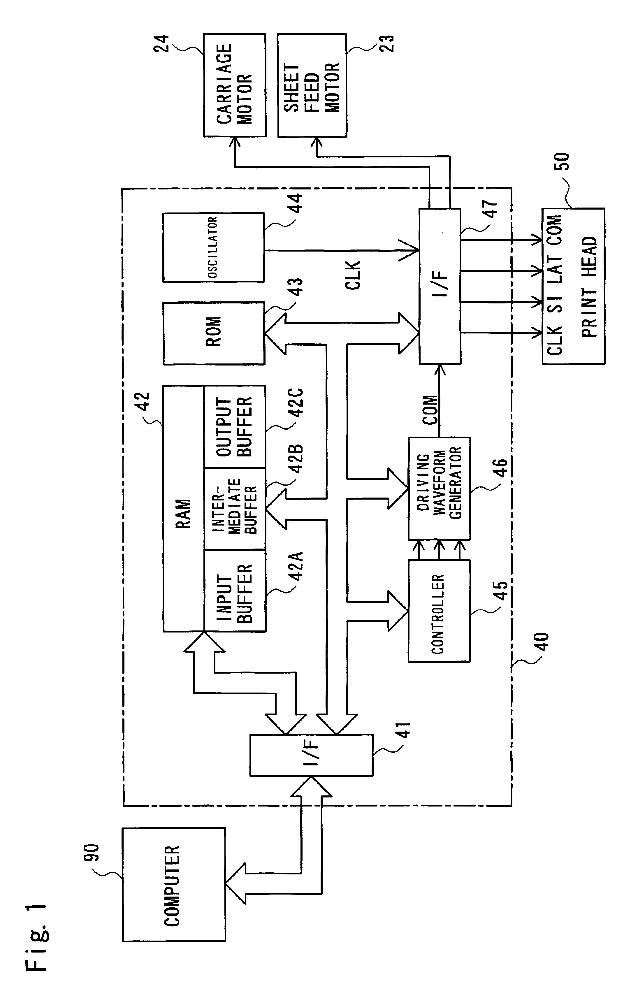
[0053]FIG. 1 is a block diagram illustrating the general structure of a printing apparatus in a first embodiment of the present invention. The printing apparatus includes a computer 90, a control circuit 40, a sheet feed motor 23, a carriage motor 24 that carries out main scan, and a print head 50. In the printing apparatus, the control circuit 40 receives a printing signal from the computer 90 to control formation of dots according to an original image and drives the respective units to print a resulting image in response to the printing signal.

[0054]The control circuit 40 includes an interface 41 that receives the printing signal output from the computer 90, a RAM 42 in which a diversity of data are stored, a ROM 43 in which a variety of processing routines for data processing are stored, an oscillator 44, a controller 45 including a CPU, a driving waveform generation circuit 46, and an interface 47 that sends the print...

second embodiment

B. Second Embodiment

[0079]While the first embodiment prevents accumulation of errors, a second embodiment of the present invention prevents an extreme variation in driving waveform due to an overflow or an underflow of the result of summation with the cumulative error.

B1. Internal Structure of Driving Waveform Generator

[0080]FIG. 8 is a block diagram illustrating the internal structure of a driving waveform generation circuit 46A in the second embodiment of the present invention. The difference from the driving waveform generation circuit 46 of the first embodiment is that an anti-inversion circuit 65 functioning as a circuit of modifying the result of summation is disposed between the adder 64 and a second latch 66A. When there is an overflow or an underflow in the result of summation by the adder 64, the anti-inversion circuit 65 corrects the result of summation to a value within an available range of the adder 64 and outputs the modified value to the second latch 66A. In order to...

third embodiment

C. Third Embodiment

[0101]FIG. 13 is a block diagram illustrating the internal structure of a driving waveform generation circuit 46B in a third embodiment of the present invention. The driving waveform generation circuit 46B corresponds to a combination of the first embodiment with the second embodiment. In the driving waveform generation circuit 46B of the third embodiment, the anti-inversion circuit 65 is disposed between the adder 64 and the second latch 66 like the second embodiment, while the floor signal FLOOR is input into the second latch 66 like the first embodiment.

[0102]The anti-inversion circuit 65 carries out the operations as discussed in the second embodiment, while the second latch 66 carries out the operations as discussed in the first embodiment. Namely the lower 8 bits in the result of summation are periodically cleared by the second latch 66 in synchronism with the floor signal FLOOR. The anti-inversion circuit 65 prevents an overflow and an underflow in the resu...


PUM


Abstract

The present invention provides a technique that prevents a shift of a driving waveform due to accumulation of errors in a process of generating the driving waveform to drive driving elements on a print head. The technique of the present invention successively sums up a plurality of gradient data at a preset calculation period to give a result of summation and carries out digital-to-analog (D-A) conversion with regard to only specific upper columns in the result of summation in synchronism with the preset calculation period, so as to generate a driving waveform. Each gradient data represents a local gradient of the driving waveform and is stored in a memory. In the process of generating the driving waveform, the technique of the present invention corrects the result of summation to a preset value under a predetermined condition. One preferable embodiment clears specific lower bits in the result of summation in synchronism with a floor signal. Another preferable embodiment forcibly corrects the result of summation to an upper limit value or a lower limit value of a preset range when the result of summation exceeds the preset range. Such correction effectively cancels the potential effects of cumulative error on the driving waveform.

Description

BACKGROUND OF THE INVENTION[0001]1. Field of the Invention[0002]The present invention relates to a technique of generating a driving waveform to activate a driving element.[0003]2. Description of the Related Art[0004]Ink jet printers are a known output device of the computer. The ink jet printer causes preset quantities of inks to be ejected from nozzles provided on a print head and create dots on a printing medium, thus printing a multi-color, multi-tone image. One recently proposed technique changes the quantity of ink ejection among a plurality of different levels, in order to attain the smooth tone expression.[0005]Ink ejection is carried out in response to output of a predetermined voltage signal to driving elements provided on the print head, that is, a driving waveform. In the case where piezoelectric elements are applied for the driving elements, the driving waveform controls operations of the piezoelectric elements and regulates the quantity of ink ejection.[0006]A programm...

Claims


Application Information

Patent Timeline
Patent Type & Authority Patents(United States)
IPC IPC(8): B41J2/045H03K4/02H03K4/00
CPCB41J2/04508B41J2/04541H03K4/026B41J2/04581B41J2/04588B41J2/04573
Inventor FUKANO, TAKAKAZUTAMURA, NOBORUASAUCHI, NOBORUYOSHIDA, MASAHIKONISHIHARA, YUICHIKATAYAMA, TOSHIHIKO
Owner SEIKO EPSON CORP
Learn More