
Engine mounting structure

a technology for engine mounting and chassis, applied in the direction of shock absorbers, roofs, jet propulsion mounting, etc., can solve the problems of affecting the riding comfort and quality of the vehicle, affecting the coupling strength of the chassis bracket mounting part of the front side member, and the difficulty in further reducing vibration through material or structural changes of the bush, so as to effectively suppress engine vibration and noise, and reduce the amount of vibration

Inactive Publication Date: 2005-05-03
HYUNDAI MOTOR CO LTD
View PDF31 Cites 7 Cited by
  • Summary
  • Abstract
  • Description
  • Claims
  • Application Information

AI Technical Summary

Benefits of technology

[0004]The present invention provides a vehicular engine mounting structure for improving the amount of engine vibration primarily absorbed by a bush, making a chassis bracket easily mounted in an application of the bush, and increasing the internal strength of a front side member part where the chassis bracket is mounted, thereby reducing the amount of engine vibration transmitted to the interior of the vehicle and improving riding comfort and interior sound of the vehicle.
[0007]Therefore, the bush can absorb greater amount of vibration and the coupling strength of the chassis bracket mounting part of the front side member is improved. As a result, the present invention is more advantageous in effectively suppressing the engine vibration and noise in the interior of the vehicle.

Problems solved by technology

The vibration caused by the engine and noise level within the interior of the vehicle affects the riding comfort and quality of the vehicle.
However, these rubber bushes absorb vibration by elasticity of the embedded rubber, making it difficult to further reduce vibration through material or structural changes of the bush.
The additional members increase the cost and complexity of the mounting structure.
Such engine vibration input parts are poorly constructed resulting in poor strength and insufficient insulation from the vibration.

Method used


Image

  • Engine mounting structure
  • Engine mounting structure
  • Engine mounting structure

Examples


Embodiment Construction

[0014]As shown in FIG. 1, a bush 40 according to the present invention has a circular shape. An end of engine bracket 41 is fastened to the bush 40 at a bolt formed at the center point of the upper side of the bush 40, thereby connecting the engine 10 to the chassis.

[0015]The bush 40 may be made of elastic rubber, or a liquid sealed type of elastic rubber material where liquid is contained to generate a damping force by fluidity. By keeping its absorbing capacity constant regardless of directions of input vibration the bush 40 has better vibration absorption capabilities. (There is no difference in the amount of vibration to be absorbed by reducing horizontal and vertical vibration.)

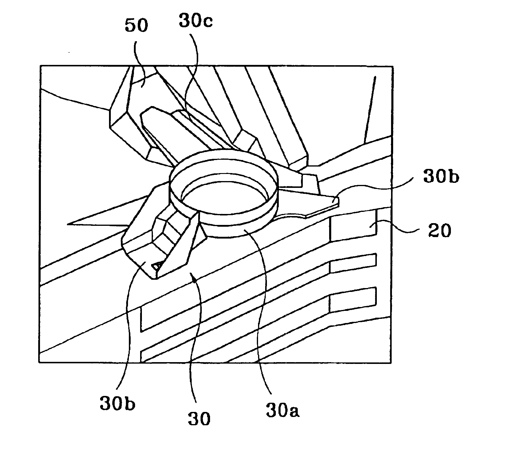
[0016]The chassis bracket 30 is formed with a circular supporting part 30a at the center thereof, attachment parts 30b at both sides of the supporting part 30a, and a stay 30c between the attachment parts 30b. The bush 40 is compressed and attached to the chassis at the supporting part 30a. The attachmen...


PUM


Abstract

The vehicular engine mounting structure includes a liquid sealed type bush instead of a rubber embedded bush. The mounting structure also includes: a chassis bracket having a circular supporter for receiving the bush. Two attachment parts of the chassis bracket are coupled to at a front side member. Vertical reinforcing members and a connection reinforcing member for supporting the vertical reinforcing members are installed in the front side member.

Description

FIELD OF THE INVENTION[0001]The present invention relates to an engine mounting structure, and more particularly, to a vehicular engine mounting structure. The vehicular engine mounting structure improves performance of an engine mounting bush and absorbs vibration at a vibration input unit where engine vibration is transferred to a vehicular body.BACKGROUND OF THE INVENTION[0002]The vibration caused by the engine and noise level within the interior of the vehicle affects the riding comfort and quality of the vehicle. As a result, new vehicular engine mounting structures have been developed to better absorb vibration.[0003]Conventional mounting structures mount to a vehicle chassis via a rubber bush. However, these rubber bushes absorb vibration by elasticity of the embedded rubber, making it difficult to further reduce vibration through material or structural changes of the bush. Furthermore, it is generally necessary to include additional members to reinforce and support the mount...

Claims


Application Information

Patent Timeline
IPC IPC(8): F16F1/38B62D25/20B60K5/12B62D25/08
CPCF16F1/3849B60K5/12
Inventor KIM, KI-CHANG
Owner HYUNDAI MOTOR CO LTD
Learn More