
Speed signal variance detection fault system and method

a fault system and speed signal technology, applied in the field of turbine engines, can solve problems such as noisy signal, unreliable conventional signal frequency change rate test used to detect intermittent or “in-range” failures, and multiple crossings

Inactive Publication Date: 2005-04-26
HONEYWELL INT INC
View PDF22 Cites 6 Cited by
  • Summary
  • Abstract
  • Description
  • Claims
  • Application Information

AI Technical Summary

Benefits of technology

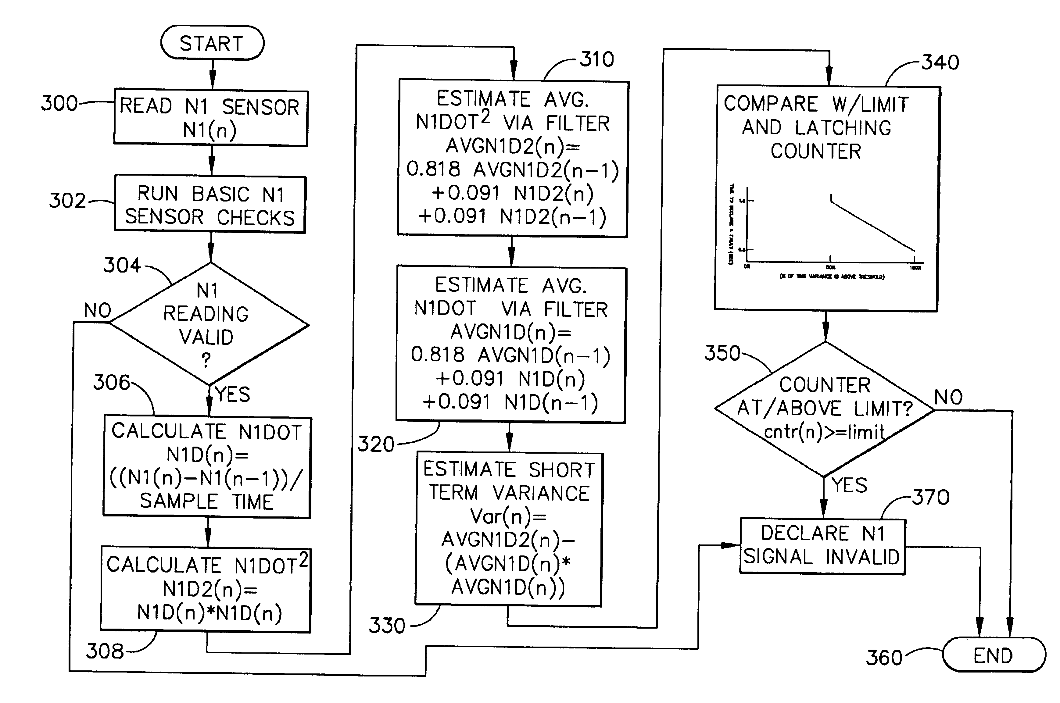
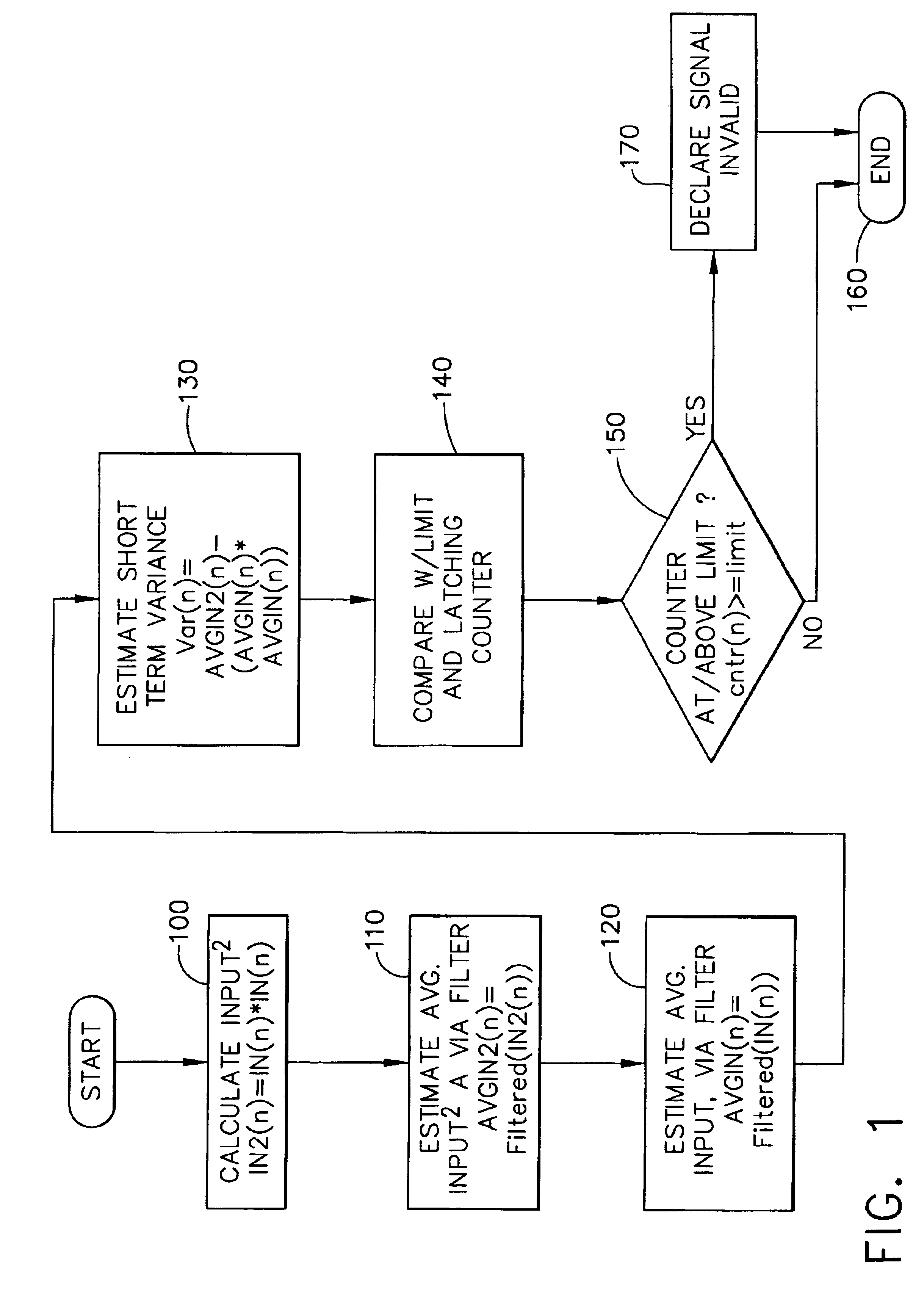
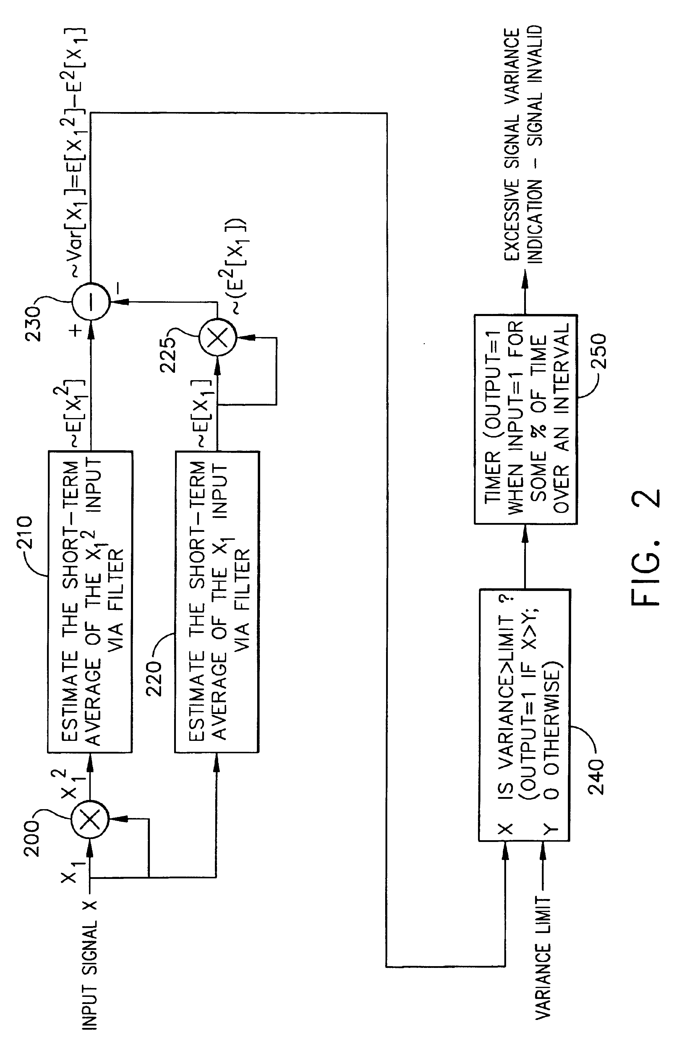
[0006]In one aspect of the present invention, a system useable in electrical control sensors for shaft speed signal frequency change rate tests, detects intermittent or “in-range” failures. It has means for measuring frequency of a shaft speed signal; means for estimating a short-term variance (standard deviation) of the measured signal using the equation: Var[x]=E[x]−E2[x], where E[x2] is an estimated average ...

Problems solved by technology

The conventional signal frequency change rate tests used to detect intermittent or “in-range” failures are unreliable because they either often detect failures that do not truly exist (false alarms) or, in order to avoid generation of false alarms, they miss real failure events.
First failure mode includes intermittent electrical sensor failures that cause a noisy signal.
Second failure mode includes internal sensor failures which can cause “multiple crossings” or cases where higher than normal speeds are read occasionally.
Third failure mode includes damaged gear teeth, shaft runout or excessive speed pickup installation gaps, and can cause “missed teeth” and resultant speed measurement errors.
On turbofans, the fourth failure mode is a catastrophic engine failure event called a “blade out”, which causes the controller to perceive speed incorrectly and fuel the engine up.

Method used


Image

  • Speed signal variance detection fault system and method
  • Speed signal variance detection fault system and method
  • Speed signal variance detection fault system and method

Examples


Embodiment Construction

[0016]The following detailed description is of the best currently contemplated modes of carrying out the invention. The description is not to be taken in a limiting sense, but is made merely for the purpose of illustrating the general principles of the invention, since the scope of the invention is best defined by the appended claims.

[0017]The present invention includes a speed signal variance detection fault logic system and method, available for signal frequency change rate tests, used to detect intermittent or “in-range” failures. It is more reliable than reasonableness rate tests, due to better failure detection with fewer false alarms. Moreover, it is less complex because it avoids the use of complex missing tooth detectors.

[0018]Although developed for compressor and load shaft speed parameters of gas turbine engines, the method and system of the present invention can be applied for testing other sensed signals, such as exhaust gas temperature (EGT) probes signals. An example o...


PUM


Abstract

A method and a system is provided, useable in electrical control sensors for shaft speed signal frequency change rate tests, detecting intermittent or “in-range”failures. The method estimates a short-term variance of the measured signal or signal rate of change, using the equation: Var[x]=E[x2]−E2[x], where E[x2] is an estimated average of the squared measured signal or rate of change over the short term, and E2[x] is a squared estimated average of the measured signal or rate of change over the short term. The estimated variance is compared with a predefined variance limit for a predefined amount of time, and if the estimated variance exceeds the predefined variance limit for the predefined amount of time, the measured signal is deemed invalid. A latching counter is used for timing, and its time out rate is preferably proportional to the time period the measured input is true. The step for estimating a short-term variance of the measured signal uses several filters performing averaging function.

Description

CROSS REFERENCE TO RELATED APPLICATION[0001]This is a divisional application of U.S. application Ser. No. 09 / 815,177 filed Mar. 21, 2001, now U.S. Pat. No. 6,633,828.BACKGROUND OF THE INVENTION[0002]The present invention generally relates to turbine engines and, more particularly, to a method and system used in electrical control sensors for shaft speed signal frequency change rate tests.[0003]Compressor and load shaft speeds are the primary control parameters of gas turbine engines. Accurate speed measurement is essential for proper engine control. In modern engines with electronic control systems, shaft speeds are typically measured using passive variable reluctance magnetic speed sensors, which sense passing of gear teeth or similar objects. The sensors output an electrical signal to the gas turbine electronic control unit (ECU), with signal frequency proportional to the shaft speed (i.e., passing speed of the gear teeth). The ECU measures the speed by measuring the frequency of ...

Claims


Application Information

Patent Timeline
IPC IPC(8): G05B9/02
CPCG05B9/02F05B2270/101F05B2270/304
Inventor FAYMON, DAVEXIONG, YUFEIRUSHINSKY, JOHN
Owner HONEYWELL INT INC
Learn More