Low power wireless network
a low-power wireless network and wireless network technology, applied in the field of wireless communication, can solve the problems of significant reduction of the power used by a portable computer or other mobile computing electronic device, and achieve the effects of reducing the power used, eliminating the effect of obstruction, and reducing the power requiremen
- Summary
- Abstract
- Description
- Claims
- Application Information
AI Technical Summary
Benefits of technology
Problems solved by technology
Method used
Image
Examples
first embodiment
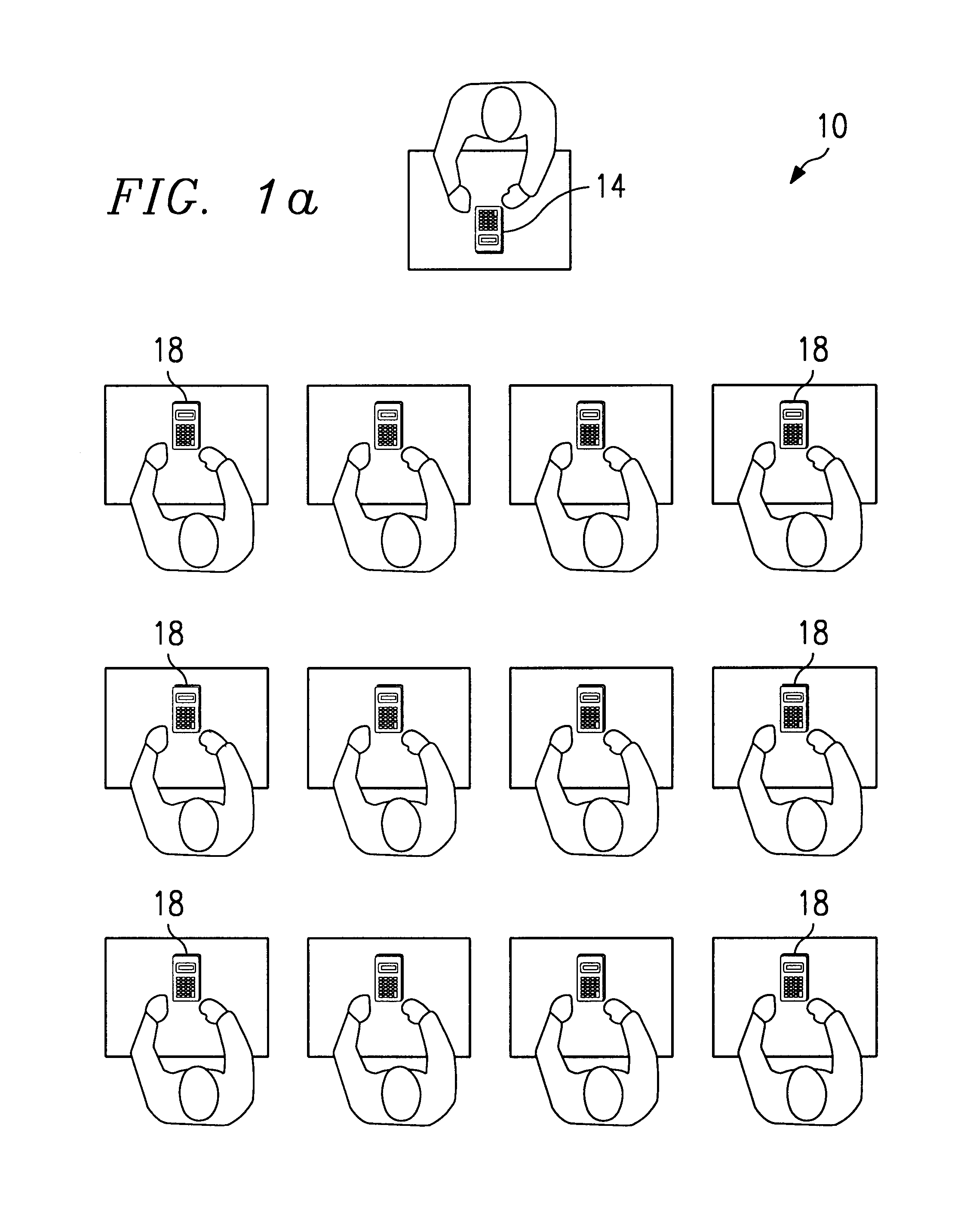
[0032]FIGS. 2a and 2b illustrate a first embodiment to reduce the power needed to communicate between a mobile computing electronic device and a base station in a classroom situation such as shown in FIG. 1.
[0033]In FIG. 2a, a class room setting 30 comprises a teacher's desk 32 and a plurality of student desks 34. The desks 30 and 32 can be arranged in any manner. The teacher's calculator (base calculator 36) is located on the teacher's desk 32 and the student calculators (client calculators 38) are located on the student desks 34. A distributed antenna 40 has segments 42 which extend onto the student desks 34. In the preferred embodiment, the base calculator 36 is hard wired to the antenna 40. The segments 42 may be exposed on an outer surface of the desks 32 and 34 (typically underneath the desktops) or, alternatively, the segments 42 may be embedded into the material used to form the desktops, insofar as the material does not shield the antenna segments 42 from radio frequency si...
third embodiment
[0052]FIG. 5 illustrates a third embodiment where the distributed antenna system 40 is disposed on or in ceiling tiles. In this embodiment, the distributed antenna system 40 is formed on wired ceiling tiles 62, such as those commonly used in office environments. Each antenna-wired ceiling tile 62 provides a length of antenna wire for forming a portion of the distributed antenna system 42. Non-wired ceiling tiles 64 can also be used to form the ceiling where an antenna is not needed. The ceiling tiles 62 and 64 are held in place by supports 66. An access point 24 is connected to the antenna system 40 by physical connection.
[0053]In operation, the wired ceiling tiles 62 have different configurations to form a distributed antenna system 42 of a desired configuration. For example, wired ceiling tiles 62a incorporate an antenna wire which runs the length of the ceiling tile, where ceiling tiles 62b incorporate connected length-wise and width wise antenna wires. Ceiling tiles 62c incorpor...
second embodiment
[0058]FIG. 6b illustrates a connector which can be used to connect antenna wires 63 as the ceiling tiles are placed on the support members 66. In this embodiment, support members 66 have conducting regions 72, surrounded by dielectric regions 74 (not necessary if the support members themselves are formed of a dielectric material such a plastic). The antenna wires 63 are terminated with conducting spring clips 76 which create a firm contact with conducting regions 72 when the ceiling tiles 62 are placed on the support members 66.
[0059]In operation, as ceiling tiles 62 are placed in the support members 66, the conducting regions 72 form a physical low resistance connection between the antenna wires 63 associated with adjacent ceiling tiles 62. Thus, a desired antenna pattern can be easily implemented or changed simply by placing selected ceiling tiles 62 in the support members 66.
[0060]The embodiments shown in FIGS. 2-6 provide significant advantages over the prior art. The power requ...
PUM
 Abstract
Description
Claims
Application Information
 - R&D
- Intellectual Property
- Life Sciences
- Materials
- Tech Scout
- Unparalleled Data Quality
- Higher Quality Content
- 60% Fewer Hallucinations
Browse by: Latest US Patents, China's latest patents, Technical Efficacy Thesaurus, Application Domain, Technology Topic, Popular Technical Reports.
© 2025 PatSnap. All rights reserved.Legal|Privacy policy|Modern Slavery Act Transparency Statement|Sitemap|About US| Contact US: help@patsnap.com


