
Method of manufacturing and disk drive produced by measuring the read and write widths and varying the track pitch in the servo-writer

a technology of servo-writer and read and write width, applied in the direction of maintaining head carrier alignment, recording information storage, instruments, etc., can solve the problems of wasting enhanced capability, long time to servo-write each disk drive, and troublesome presence of separate read and write elements

Inactive Publication Date: 2005-04-26
WESTERN DIGITAL TECH INC
View PDF7 Cites 134 Cited by
  • Summary
  • Abstract
  • Description
  • Claims
  • Application Information

AI Technical Summary

Problems solved by technology

The servo-writing process is a manufacturing bottleneck because each HDA must remain in the STW for an extensive amount of time in order to step, wait, and record each pass that collectively make up the required servo information.
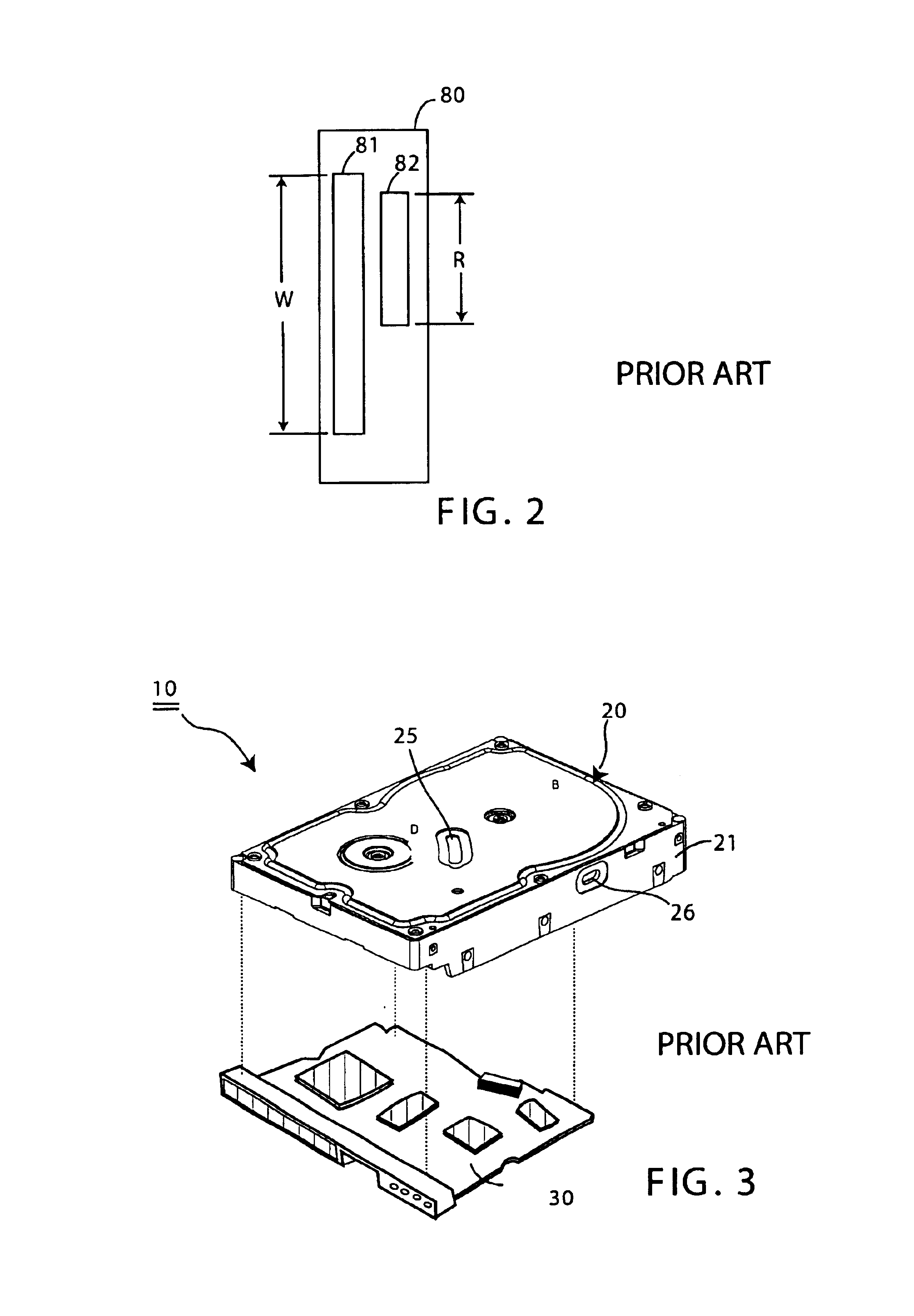
The presence of separate read and write elements coupled with the wide variability of read width R and write width W is particularly troublesome as it relates to the servo-writing process and narrow range of widths that may presently be used.
The servo-writing process is of major concern because STWs are so expensive (upward of $100,000) that only limited numbers can be used and it takes a long time to servowrite each disk drive (several minutes per drive).
Some heads could be used with narrower tracks, but their enhanced capability is wasted with the nominal TPI, or worse, they are discarded altogether;it is difficult to accurately identify this small subset of heads with currently available measurement techniques so, even if the heads are “binned” by making such measurements, many of the drives fail at a very late stage of the manufacturing process (after assembly of the HDA, servo-writing, mounting of the controller board and while testing the drive during Initial Burn-In or IBI), because one or more of the heads is too narrow or too wide.
These failed drives must generally make a second trip through the servo-writing process, an unfortunate and expensive occurrence.

Method used


Image

  • Method of manufacturing and disk drive produced by measuring the read and write widths and varying the track pitch in the servo-writer
  • Method of manufacturing and disk drive produced by measuring the read and write widths and varying the track pitch in the servo-writer
  • Method of manufacturing and disk drive produced by measuring the read and write widths and varying the track pitch in the servo-writer

Examples


Embodiment Construction

[0034]This patent application is directed to a new, innovative method of manufacturing a disk drive and to a disk drive made in accordance with the method.

[0035]FIG. 6 is a flowchart of a preferred method of manufacturing a disk drive according to this invention. The illustrated method operates on an HDA 20 like that shown in FIGS. 1 and 3, i.e. an HDA 20 containing at least one magnetic disk 23 with a magnetic surface and a head stack assembly 40 that includes a two-element transducer head 80. The HDA 20 is usually placed into the STW 100 in “bare” form (i.e. without the controller circuit board 30), but as discussed below, it may be desirable to marry the HDA 20 with the controller circuit board 30 before mounting the disk drive 10 in the STW 100 and recording servo tracks.

[0036]The method begins at step 210 by mounting the HDA 20 in the STW 100 for moving the HSA 40 to desired positions over the magnetic disk. FIG. 5 further illustrates this step.

[0037]At steps 220-A and 220-B, t...


PUM

PropertyMeasurementUnit
magneticaaaaaaaaaa
widthaaaaaaaaaa
widthsaaaaaaaaaa

Abstract

A method of manufacturing a disk drive and a disk drive made with such method where the width of the read element and the width of the write element are both measured at servo-writing time and the track pitch of the disk drive is set on the basis of those measurements. Disk drives with superior head width combinations are servo-written with a narrower track pitch in order to have a higher storage capacity. Disk drives with inferior head width combinations are detected before servo-writing so that the disk drive may be servo-written with wider track pitch rather than with a nominal track pitch that results in a subsequent drive failure during initial burn-in (IBI). The heads are used more efficiently in that heads that are more capable are used to their ability and less capable heads that would otherwise be disposed of are used at all. Fewer disk drives are required to be reworked and returned to the servo-writing process.

Description

BACKGROUND OF THE INVENTION[0001]1. Field of the Invention[0002]The present invention relates generally to magnetic disk drives (disk drives), and more particularly to an efficient method of manufacturing a disk drive by using a servo track writer (STW) for measuring the widths of the read and write elements to set the track pitch.[0003]2. Description of the Related Art[0004]Referring to FIG. 1, a conventional disk drive 10 has a head disk assembly (HDA) 20 including at least one disk 23, a spindle motor 22 for rapidly rotating the disk 23, and a head stack assembly (HSA) 40 that includes an actuator assembly 50 and a head gimbal assembly (HGA) (not numbered) with a transducer head 80 for reading and writing data. The HSA 40 is part of a servo control system that positions the transducer head 80 over a particular track on the disk to read or write information from that track. The HSA 40 earns its name from the fact that it generally includes a plurality of HGAs that collectively pro...

Claims


Application Information

Patent Timeline
Patent Type & Authority Patents(United States)
IPC IPC(8): G11B27/36G11B21/02H04R31/00G11B5/596
CPCG11B5/59633Y10T29/49036G11B5/59638
Inventor CODILIAN, RAFFIJOHNS, WILLIAM D.PARK, CHARLES A.NGUYEN, DAVID D.CHUE, JACK M
Owner WESTERN DIGITAL TECH INC
Learn More