
Microplate

a micro-plate and micro-plate technology, applied in the field of micro-plates, can solve the problems of difficult identification of micro-plates, affecting the quality of micro-plates, etc., and achieves the effect of easy identification and easy distinction

Inactive Publication Date: 2005-04-26
FUTABA CORPORATION
View PDF22 Cites 12 Cited by
  • Summary
  • Abstract
  • Description
  • Claims
  • Application Information

AI Technical Summary

Benefits of technology

[0011]The present invention has been made to solve the problems pointed out above. A first object of the invention is to provide a microplate that can be easily distinguished from any other. A second object of the invention is to provide a microplate with which it is easy to identify the wells.

Problems solved by technology

However, the number or mark is liable to erase when the microplate 1 is exposed heat, vapor or organic solvent or accessed to by a person or any instrument during the processes of analyzing the samples contained in the wells 2.
If this happens, it will be difficult to identify the microplate 1 and to identify any well 2 with its position on the microplate 1.
Felt-pen ink can hardly firmly stick to anything made of polypropylene.
If any person handles the microplate 1 while putting on the ink-stained rubber gloves, the liquid samples may be contaminated.
The volatile component may be dissolved into the liquid samples, inevitably influencing the results of analysis.
Obviously it is troublesome to write the number or mark with felt pens on the base 3 of the microplate 1.
Furthermore, one column number is likely to be taken for another, causing errors in identifying the wells 2, because the column numbers are printed at short intervals on the long edge of the microplate 1.

Method used


Image

  • Microplate
  • Microplate
  • Microplate

Examples


first embodiment

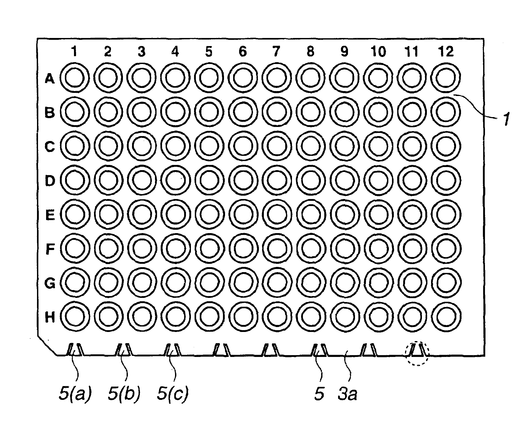
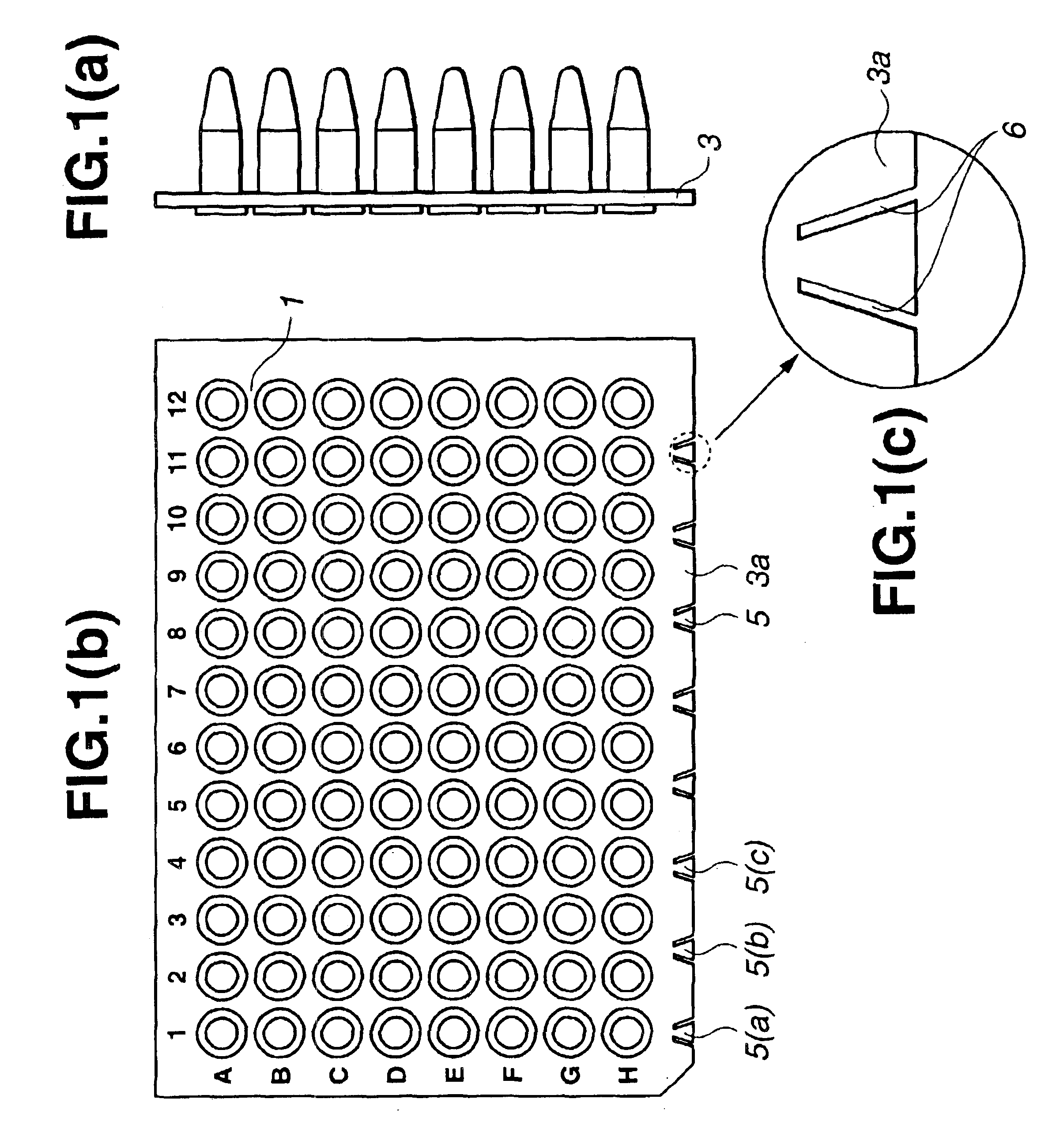
[0024]FIGS. 1A, 1B and 1C show a microplate 1 according to the present invention. FIG. 1A is a side view of the microplate 1, and FIG. 1B is a plan view thereof. The microplate 1 is identical in basic structure to the conventional one illustrated in FIGS. 6A and 6B. Hence, the components similar or identical to those of the conventional microplate are designated at the same reference numerals and will not be described in detail. As shown in FIG. 1B, the base 3 of the microplate 1 has mark parts 5 that are provided at a long edge 3a. FIG. 1C is a magnified view depicting one of the mark parts 5. As shown in FIG. 1C, two elongate notches 6 are cut in each mark part 5. The notches 6 incline such that they are most spaced at the edge of the base 3 and least spaced at a position near the wells. In other words, the distance between the notches 6 gradually decreases from the edge of the base 3 toward the wells. Thus, each mark part 5 is trapezoidal, with its base flush with the edge of the...

second embodiment

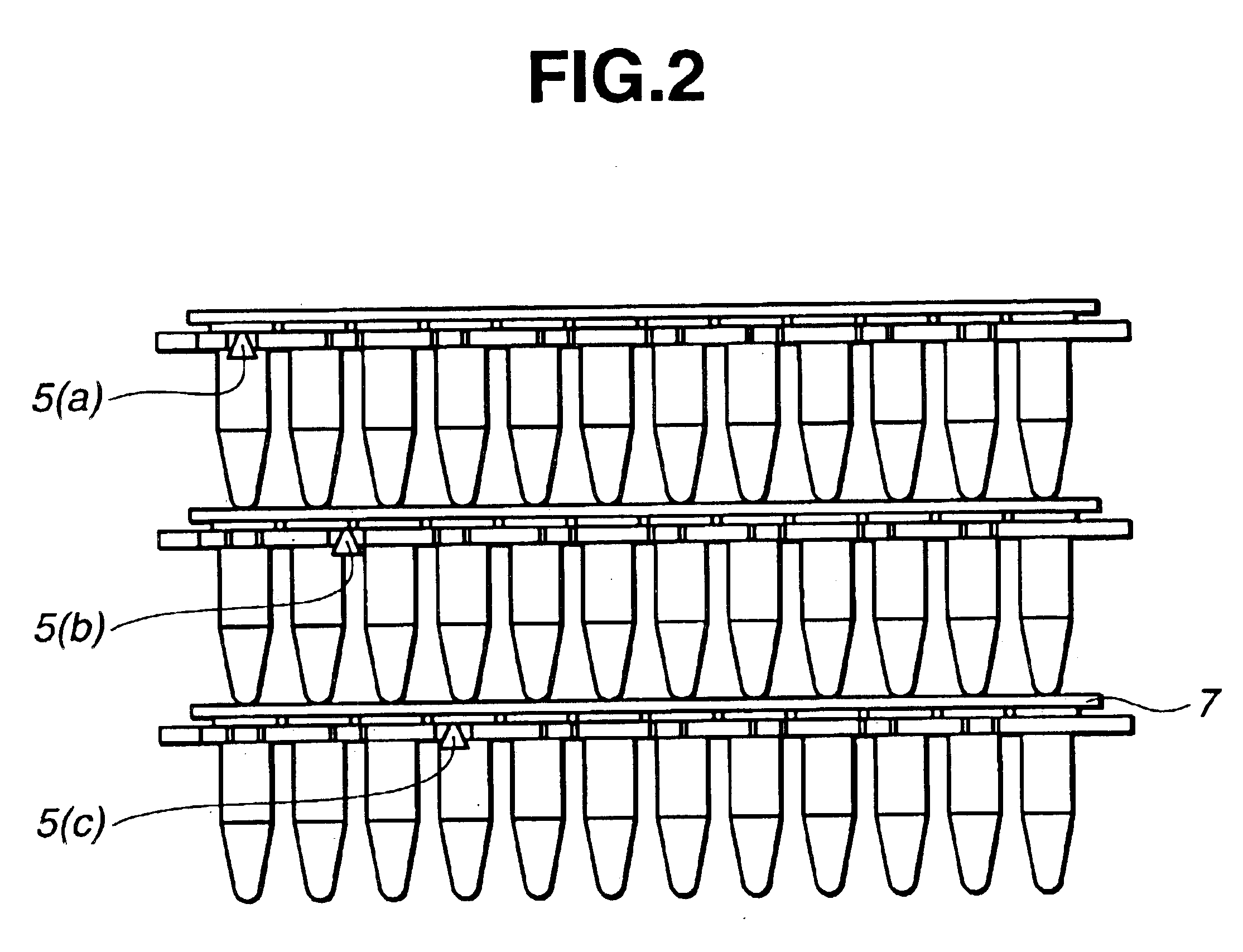
[0036]The microplate according to this invention has mark parts provided at the edges of the base, some of the mark parts aligned with the rows of wells and the remaining mark parts aligned with the columns of wells. The mark parts can therefore be used as indicia that serve to identify not only the microplate but also the respective wells. If any two mark parts are used, one provided at one edge and the other provided at the neighboring edge, the wells can be identified in 2n ways at most, where n is the number mark parts provided.

[0037]The microplate according to the third embodiment of this invention has mark parts provided at the edges of the base, some of the mark parts aligned with the rows of wells and the remaining mark parts aligned with the columns of wells. Further, the rims of the wells of every other column are colored. Hence, people can visually identify the wells more easily than with the microplate according to the second embodiment.


PUM


Abstract

A microplate having a base and wells is disclosed. The base has mark parts at least on one edge thereof. Each mark part is defined by notches cut in the edge of the base. The wells are provided in the base and arranged in rows and columns. The mark parts can be used as indicia for identifying not only the microplate but also the wells so that the microplate and the wells can be easily identified without writing numerals or marks on the edges of the base with a felt pen or the like.

Description

BACKGROUND OF THE INVENTION[0001]1. Field of the Invention[0002]The present invention relates to a microplate for use in examining samples in the course of clinical examination, DNA analysis and the like.[0003]2. Description of the Related Art[0004]Microplates are vessels widely used in clinical examination, DNA analysis and the like. A microplate has a well, in which a small amount of a liquid sample or a liquid reagent may be contained. There is known such a method that a liquid sample contained in the well of a microplate is subjected to a reaction such as heat cycle or centrifugal separation, a light beam is applied to the liquid sample, and the intensity of the light passing through the sample is measured to determine the results of the reaction. In this method, the composition of the sample and the content of each component thereof can be determined. Inasmuch as a very small amount of a sample or a reagent is required in this method, the method is widely employed to examine bl...

Claims


Application Information

Patent Timeline
IPC IPC(8): B01L3/00G01N37/00C12M1/00
CPCB01L3/5085B01L9/50Y10S436/809B01L9/56
Inventor SUZUKI, HIDEYUKISEKINE, YOSHIKATUKURAMOTO, HISAOKANEKO, MAKI
Owner FUTABA CORPORATION
Learn More