Variable inertia flywheel

a flywheel and variable inertia technology, applied in the direction of mechanical hybrid vehicles, dynamo-electric machines, electrical devices, etc., can solve the problems of greater failure probability during working life, lack of responsiveness of known mechanical and electro-mechanical arrangements,

Inactive Publication Date: 2005-04-26
PERKINS ENGINES
View PDF25 Cites 20 Cited by
  • Summary
  • Abstract
  • Description
  • Claims
  • Application Information

AI Technical Summary

Benefits of technology

[0007]In accordance with another aspect of the present invention, a method of generating electrical power in a power generation apparatus comprises determining a load demand with a control system, transmitting a demand signal from the control system to a variable inertia flywheel, varying the inertia of the flywheel in response to the demand signal by moving fluid from a first chamber provided in the flywheel to a second chamber provided in the flywheel, the first chamber being radially spaced from the second chamber, and transferring the stored kinetic energy from the flywheel to the generator.

Problems solved by technology

However, the more moving parts any apparatus has, the greater the chance of failure during its working life.
Additionally, known mechanical and electro-mechanical arrangements lack responsiveness when dealing with a sudden increase in demand for power.

Method used


Image

  • Variable inertia flywheel
  • Variable inertia flywheel
  • Variable inertia flywheel

Examples


Embodiment Construction

[0011]The preferred embodiment described herein shows a rotating, kinetic energy storage device. The energy storage device, or flywheel, may be used with a power generation apparatus. The flywheel uses electromagnetic pumps to move electrolytic fluid between fluid chambers in order to vary the moment of inertia of the flywheel.

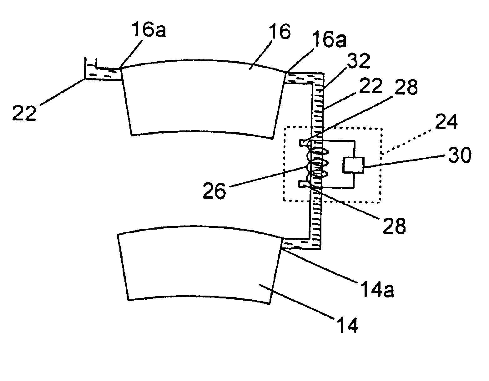
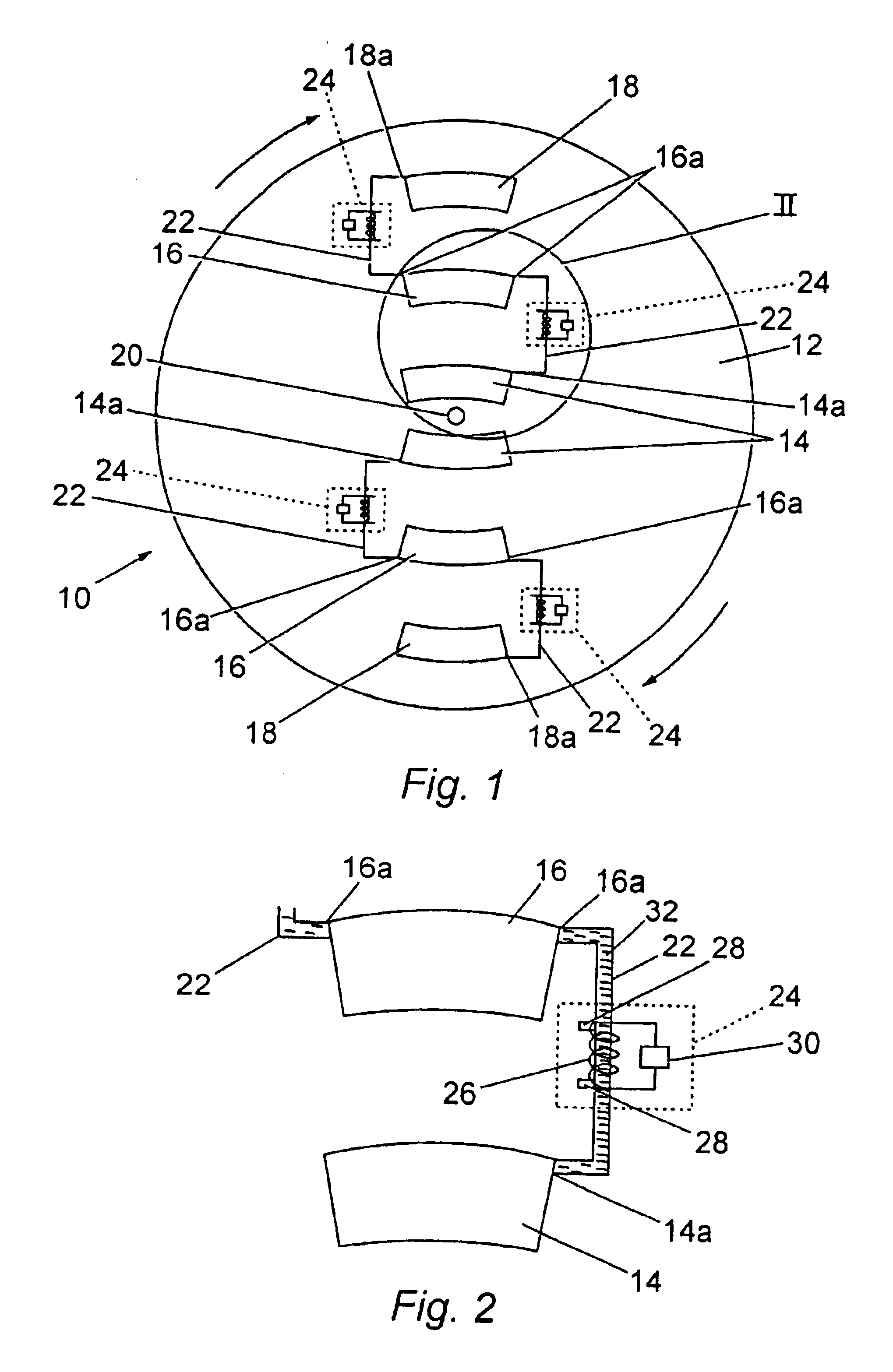
[0012]With reference to FIG. 1, there is shown a schematic view of the internal layout of a variable inertia flywheel 10. The flywheel 10 is formed from a solid disc body 12 in which are located one or more sets of chambers 14,16,18. In the embodiment described herein, the flywheel 10 is provided with a pair of fluid movement devices that are located diametrically opposite one another on the flywheel 10. Each device comprises inner 14, intermediate 16 and outer 18 chambers. The three chambers 14,16,18 are spaced from one another in a radial direction relative to the axis of rotation 20 of the flywheel 10. Each device further comprises capillary tubes, or chann...


PUM


Abstract

Variable inertia flywheels are used in power generation apparatus to quickly release stored kinetic energy to meet transient power load demands. Such flywheels typically vary inertia by using either interconnected multiple flywheels having different inertia or by mechanically moving a mass connected with the flywheel radially with respect to the axis of rotation. A variable inertia flywheel according to the present invention comprises a body and a number of fluid movement devices disposed at equal angular intervals about the rotational axis of the body. Each device comprises at least first and second chambers axially aligned in a substantially radial direction and adapted to contain an electrolytic fluid. The first and second chambers are interconnected by a channel that permits transfer of the fluid between the chambers. The movement of the fluid between the chambers is facilitated by an electromagnetic pump.

Description

TECHNICAL FIELD[0001]The present invention relates to a rotating, kinetic energy storage device, and in particular to a variable inertia flywheel utilizing electromagnetic pumps.BACKGROUND[0002]Variable inertia flywheels are utilized in rotating machinery to store energy that may be quickly released should there be a sudden energy demand. Such flywheels are common in the field of electrical power generation. Known variable inertia flywheels vary inertia either by interconnecting multiple flywheels having different inertia or by moving a mass connected with the flywheel radially with respect to the axis of rotation. The moveable mass can be a solid block or it can also be a liquid. One example, where the movement of liquid is facilitated by way of electromechanical pumps can be seen in U.S. Pat. No. 4,735,382.[0003]However, the more moving parts any apparatus has, the greater the chance of failure during its working life. Additionally, known mechanical and electro-mechanical arrangem...

Claims


Application Information

Patent Timeline
Patent Type & Authority Patents(United States)
IPC IPC(8): B60K6/10B60K6/00F16F15/30F16F15/31
CPCB60K6/105F16F15/31Y10T74/2122Y02T10/6204Y02E60/16Y02T10/62
Inventor BURSTALL, OLIVER W. J.
Owner PERKINS ENGINES
Why Eureka
Try Eureka