
Velocity matched waveguide for traveling-wave optical modulators

a technology of optical modulators and velocity matched waveguides, applied in non-linear optics, instruments, optics, etc., can solve problems such as bandwidth reduction and efficiency reduction, and achieve the effect of optimizing the operating efficiency of the modulator and effective matching the velocity of the two signals

Inactive Publication Date: 2005-04-19
AVAGO TECH WIRELESS IP SINGAPORE PTE
View PDF1 Cites 1 Cited by
  • Summary
  • Abstract
  • Description
  • Claims
  • Application Information

AI Technical Summary

Benefits of technology

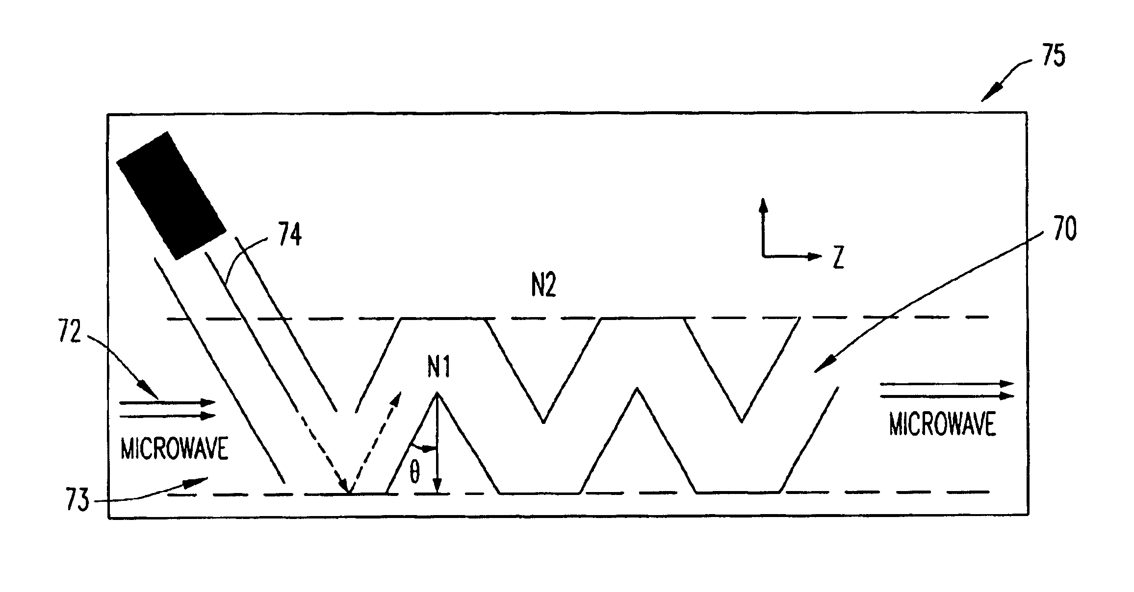
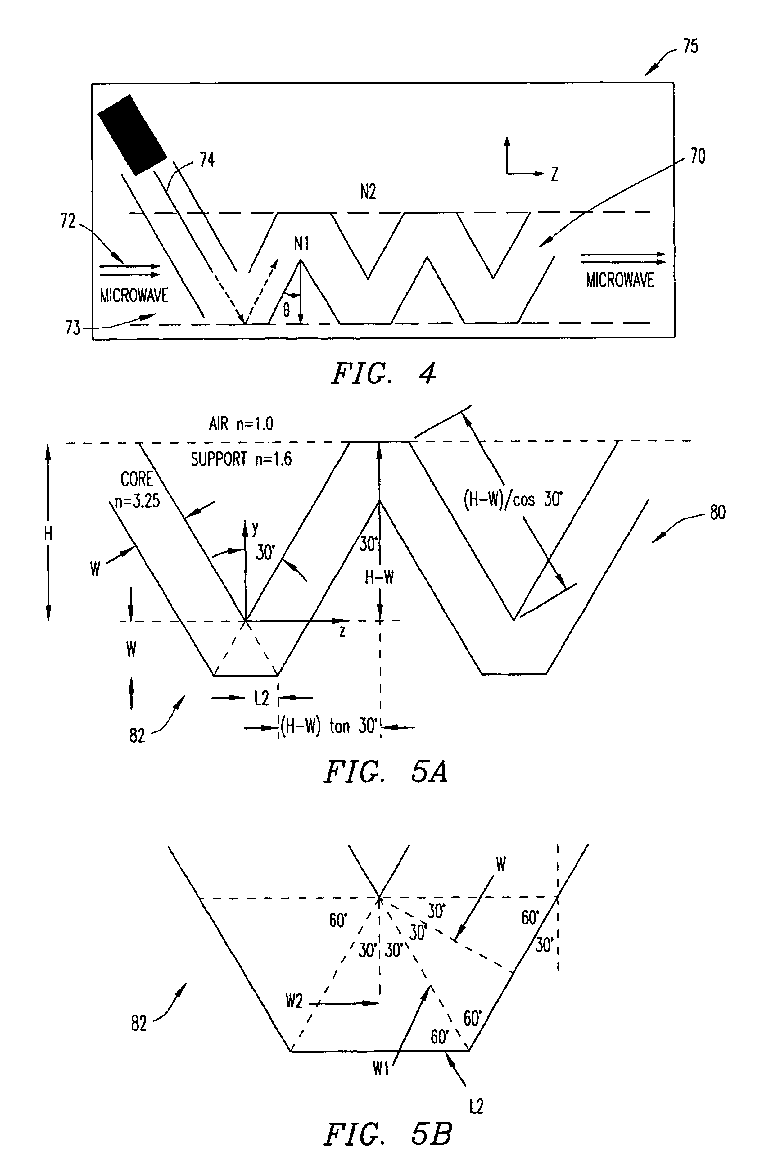
"The invention provides a method and apparatus for velocity matching an optical signal with a modulating signal in a traveling-wave optical modulator. By propagating the signals at an angle greater than zero degrees with respect to each other, the path length of at least one of the signals can be adjusted to effectively match the velocity of the two signals and optimize operating efficiency of the modulator. The technical effect is an improved velocity matching of optical signals in a traveling-wave optical modulator."

Problems solved by technology

Microwave signals and optical signals, however, may travel through the modulator at different velocities, resulting in a reduction in efficiency and bandwidth.

Method used


Image

  • Velocity matched waveguide for traveling-wave optical modulators
  • Velocity matched waveguide for traveling-wave optical modulators
  • Velocity matched waveguide for traveling-wave optical modulators

Examples


Embodiment Construction

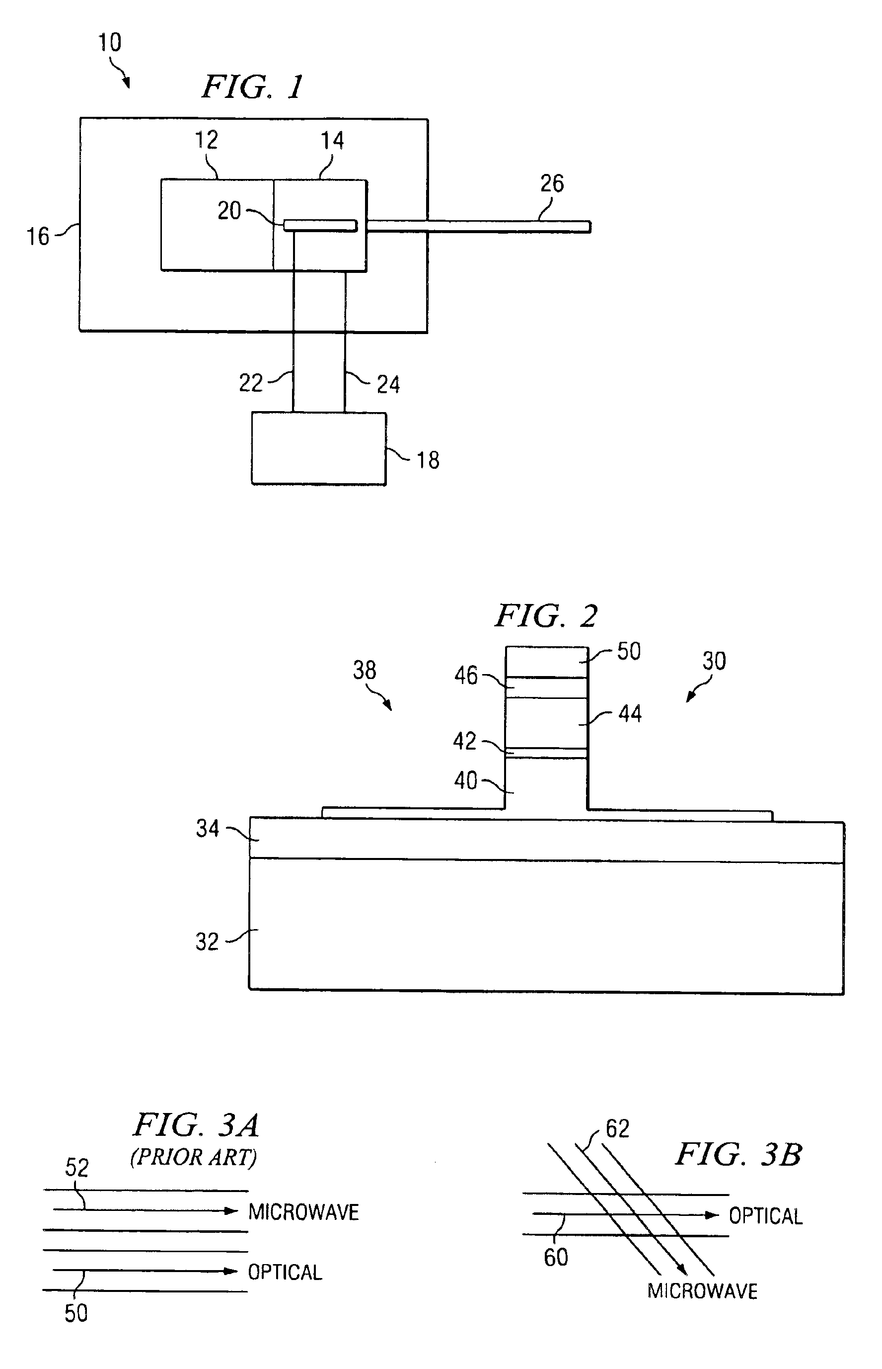
[0021]FIG. 1 is a block diagram that illustrates components of an optical communications system to assist in explaining the present invention. The optical communications system is generally designated by reference number 10, and includes light source 12, for example, a laser source, connected to optical modulator 14, such as an electro-absorptive optical modulator. The light source and the modulator are mounted to substrate 16 and are connected in such a manner that light generated by light source 12 is effectively coupled into optical modulator 14.

[0022]Data source 18 is connected to input terminal 20 of optical modulator 14 via signal wire 22 to modulate the intensity of the light that is coupled into the modulator from the light source. A circuit return between the data source and the modulator is made via return wire 24 coupled between the data source and the modulator. A modulated light signal is output from modulator 14 via optical transmission fiber 26, or the like coupled to...


PUM

PropertyMeasurementUnit
angleaaaaaaaaaa
angleaaaaaaaaaa
thicknessaaaaaaaaaa

Abstract

Method and apparatus for velocity matching an optical signal propagating in a traveling-wave optical modulator with a modulating signal. The optical signal and the modulating signal are propagated at an angle greater than zero degrees with respect to one another to adjust a path length of at least one of the signals relative to the other of the signals.

Description

BACKGROUND OF THE INVENTION[0001]1. Technical Field of the Invention[0002]The present invention relates generally to the field of optical modulation; and, more particularly, to a method and apparatus for velocity matching an optical signal propagating in a traveling-wave optical modulator with a modulating signal.[0003]2. Description of Related Art[0004]In optical communications systems, electro-optic and electro-absorptive optical modulators are often used to modulate an optical signal. One class of electrode used with electro-optic and electro-absorptive optical modulators is the “traveling-wave” type, wherein an RF electrode, such as a microwave electrode, for example, is positioned on top of or in parallel with an optical waveguiding modulator. The microwave signal represents data to be transmitted, and modulates an optical signal propagating in the waveguide by changing a property or properties of the optical signal. For example, the modulator may be configured to change the in...

Claims


Application Information

Patent Timeline
Patent Type & Authority Patents(United States)
IPC IPC(8): G02F1/035G02F1/025G02F1/01
CPCG02F1/0356G02F1/025
Inventor AMPARAN, ALFONSO B.GINES, DAVIDGRUHLKE, RUSSELL WAYNE
Owner AVAGO TECH WIRELESS IP SINGAPORE PTE
Learn More