
Threshing element for harvesters

a technology of threshing element and harvester, which is applied in the direction of mowers, agriculture tools and machines, agriculture, etc., can solve the problems of little understanding of the reactions occurring inside the threshing system, and the observation of problems, so as to achieve the effect of optimizing operational efficiency

Active Publication Date: 2014-01-23
BLUE LEAF I P INC
View PDF0 Cites 6 Cited by
  • Summary
  • Abstract
  • Description
  • Claims
  • Application Information

AI Technical Summary

Benefits of technology

This patent describes a threshing element that helps measure the forces during the process of threshing in agricultural combines or harvesters. This helps to improve the efficiency of the combine and identify any problems with the threshing system. Overall, this element helps make the threshing process more effective.

Problems solved by technology

That is, problems are observed, and changes are made based upon visual, horsepower (torque and speed), loss, wear, and other easily observed or measured parameters.
However, during operation of agricultural combines or harvesters, very little of the reactions occurring inside of threshing systems are truly understood due to the lack of access to the system.

Method used


Image

  • Threshing element for harvesters
  • Threshing element for harvesters
  • Threshing element for harvesters

Examples


Embodiment Construction

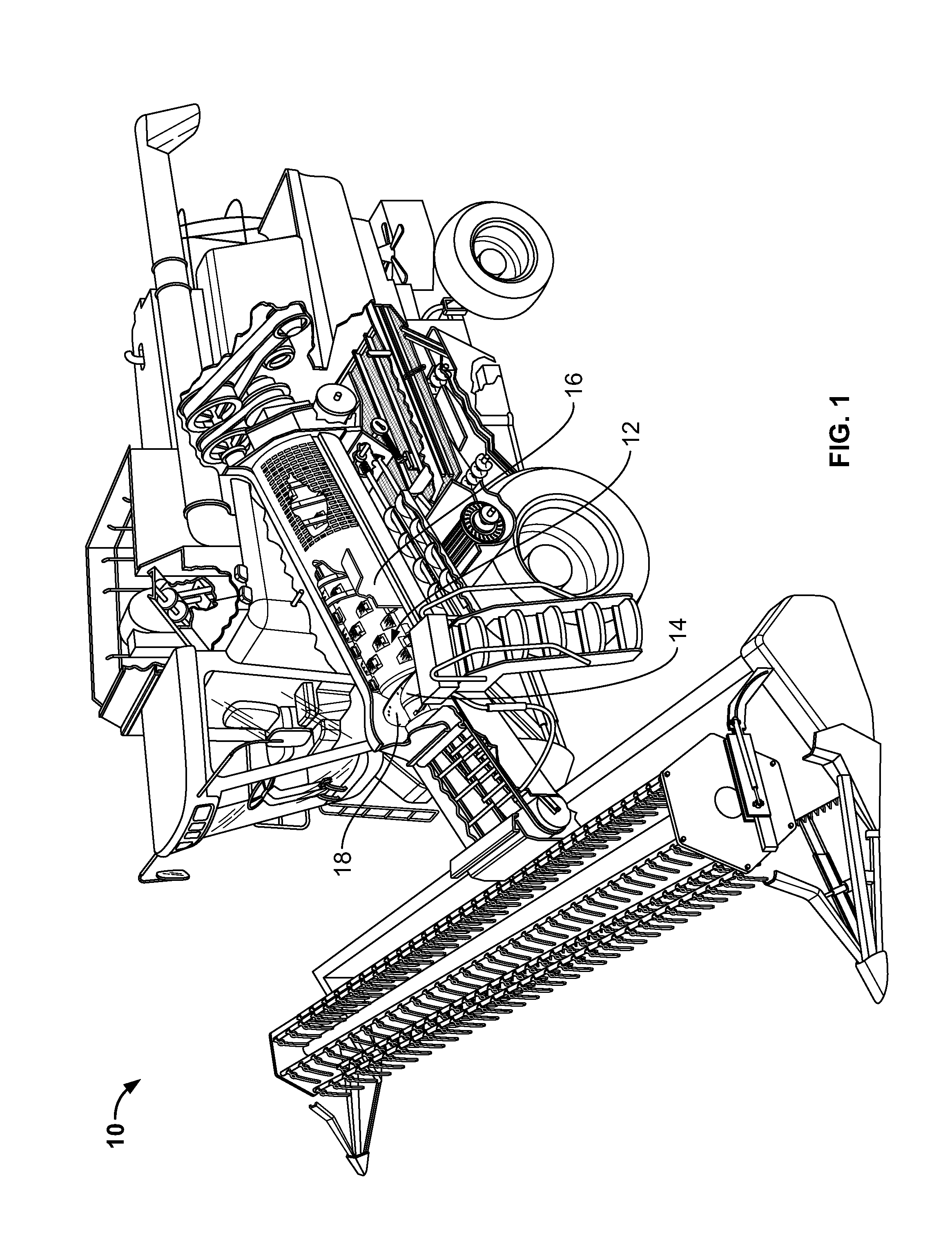
[0016]Turning now to the drawings, FIG. 1 depicts a representative agricultural combine or harvester 10 including a harvester or rotary threshing system 12 having a threshing rotor 14 in a rotor housing 16. Among other rotary threshing systems, agricultural combine or harvester 10 may have a rotary threshing system or threshing system 12 that includes only one threshing rotor (single rotor), as shown in FIG. 1, or a threshing system that has two counter-rotating threshing rotors (twin rotor). Harvester 10 is representative of an axial flow-type harvester including one or two fore and aft extending threshing rotors, but it should be understood that it is contemplated that the invention can likewise be used with rotors of other types of combines, including, but not limited to, conventional types wherein one or more rotors of the invention will be mounted in a transverse orientation within a body of the combine.

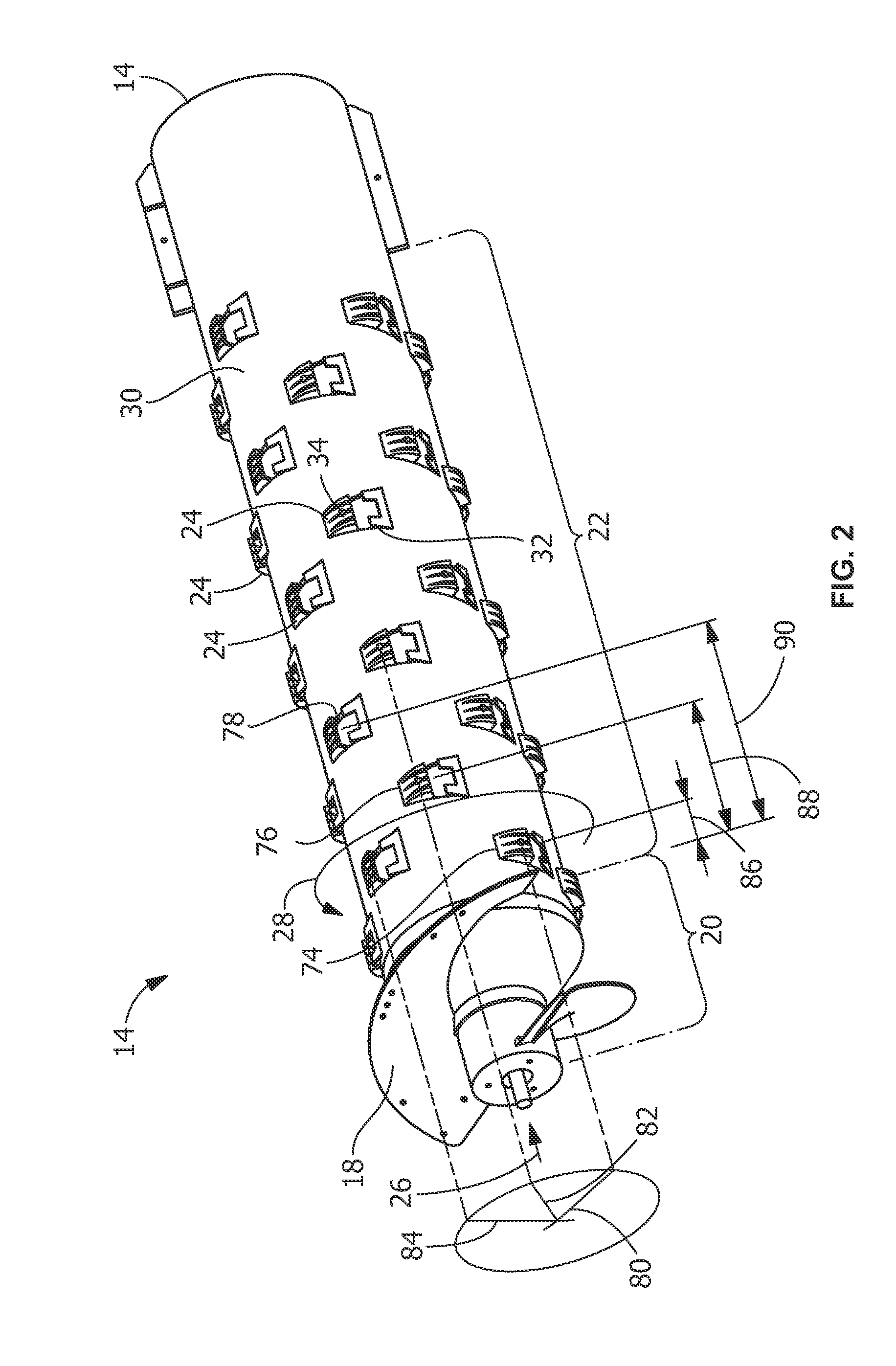
[0017]Referring collectively to FIGS. 1 and 2, threshing rotor 14 includes ...


PUM


Abstract

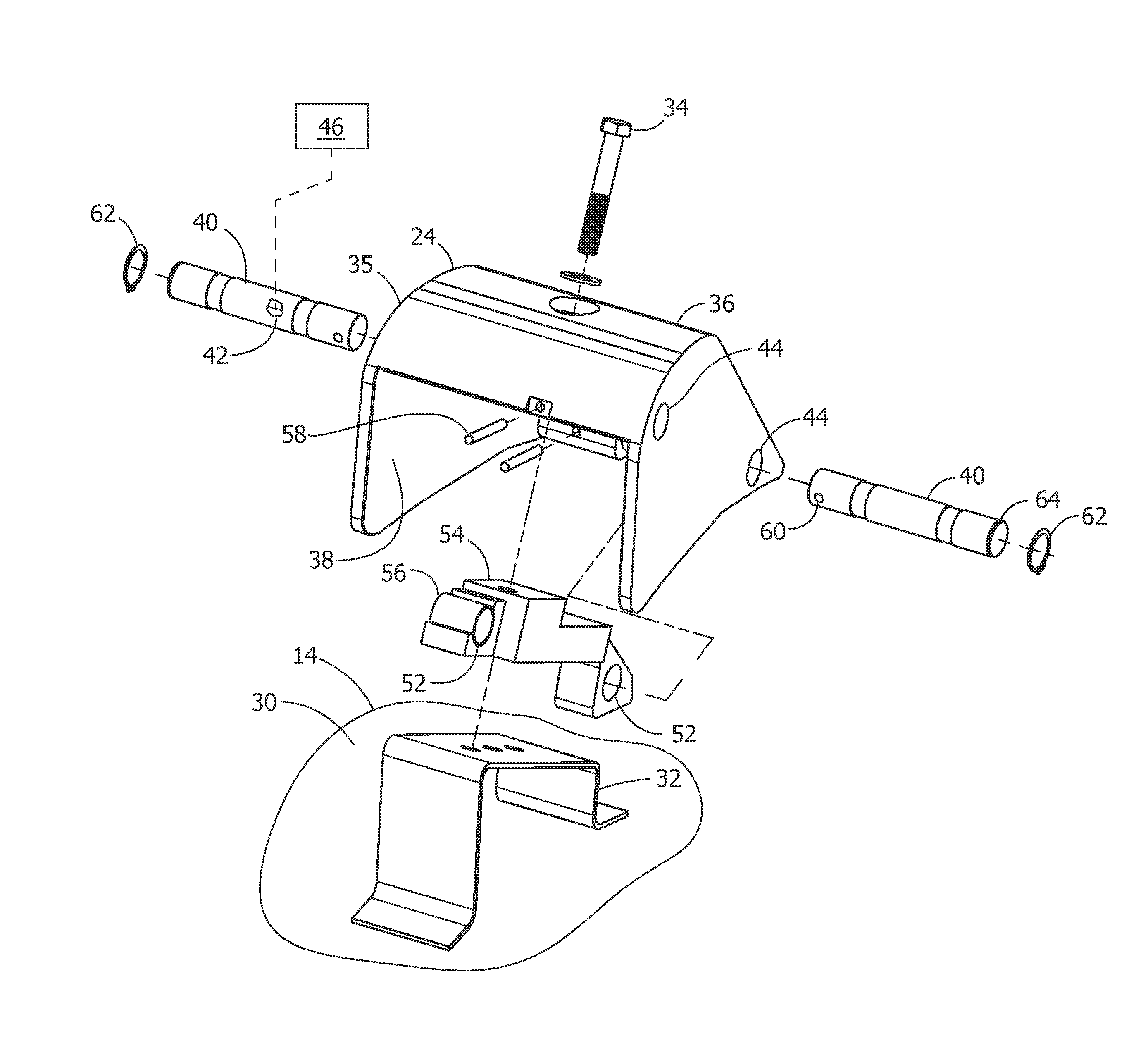
A threshing element includes a structure having an outside surface for threshing a crop material, and an inside surface. A body is operatively connected to a sensor. The body is secured to the inside surface of the structure, the body having a connecting feature for securing at least the body and the structure to each other. The structure is securable to a rotatable threshing rotor of a harvester threshing system. In response to operation of the threshing rotor of the harvester threshing system, the sensor outputs a signal corresponding to forces generated by contact between the outside surface of the structure and the crop material.

Description

FIELD OF THE INVENTION[0001]The present invention is directed to rotary threshing systems for agricultural combines or harvesters and, more particularly, to threshing elements for mounting on threshing rotors in axial flow-type combines.BACKGROUND OF THE INVENTION[0002]Many agricultural combines or harvesters use a rotary threshing and / or separating system. The system typically includes at least one rotor drivingly rotated within a rotor housing including a perforated concave spaced radially outwardly thereof. The rotor will often have a frusto-conical inlet end having a helical flight or flights therearound for conveying a flow of crop material into a space between the rotor and the housing. The main body of the rotor will typically have an array or layout of threshing elements, typically rasp bars, which protrude radially outwardly therefrom into the space for conveying a mat of the crop material along a helical path through the space. Rasp bars cooperate with the concave to separ...

Claims


Application Information

Patent Timeline
Patent Type & Authority Applications(United States)
IPC IPC(8): A01F12/28A01F7/00
CPCA01D41/1271A01F12/22
Inventor FLICKINGER, WAYNE T.ROBERGE, MARTIN J.FARLEY, HERBERT M.CEASE, HERMAN A.
Owner BLUE LEAF I P INC
Learn More