
Image transmission for low bandwidth with region of interest

a low bandwidth, image transmission technology, applied in the direction of selective content distribution, television systems, instruments, etc., can solve the problems of image data not being adapted to image data not “fitting” within the smaller display area of handheld devices, and difficulty in navigation through images

Inactive Publication Date: 2005-04-19
HEWLETT PACKARD DEV CO LP
View PDF9 Cites 114 Cited by
  • Summary
  • Abstract
  • Description
  • Claims
  • Application Information

AI Technical Summary

Benefits of technology

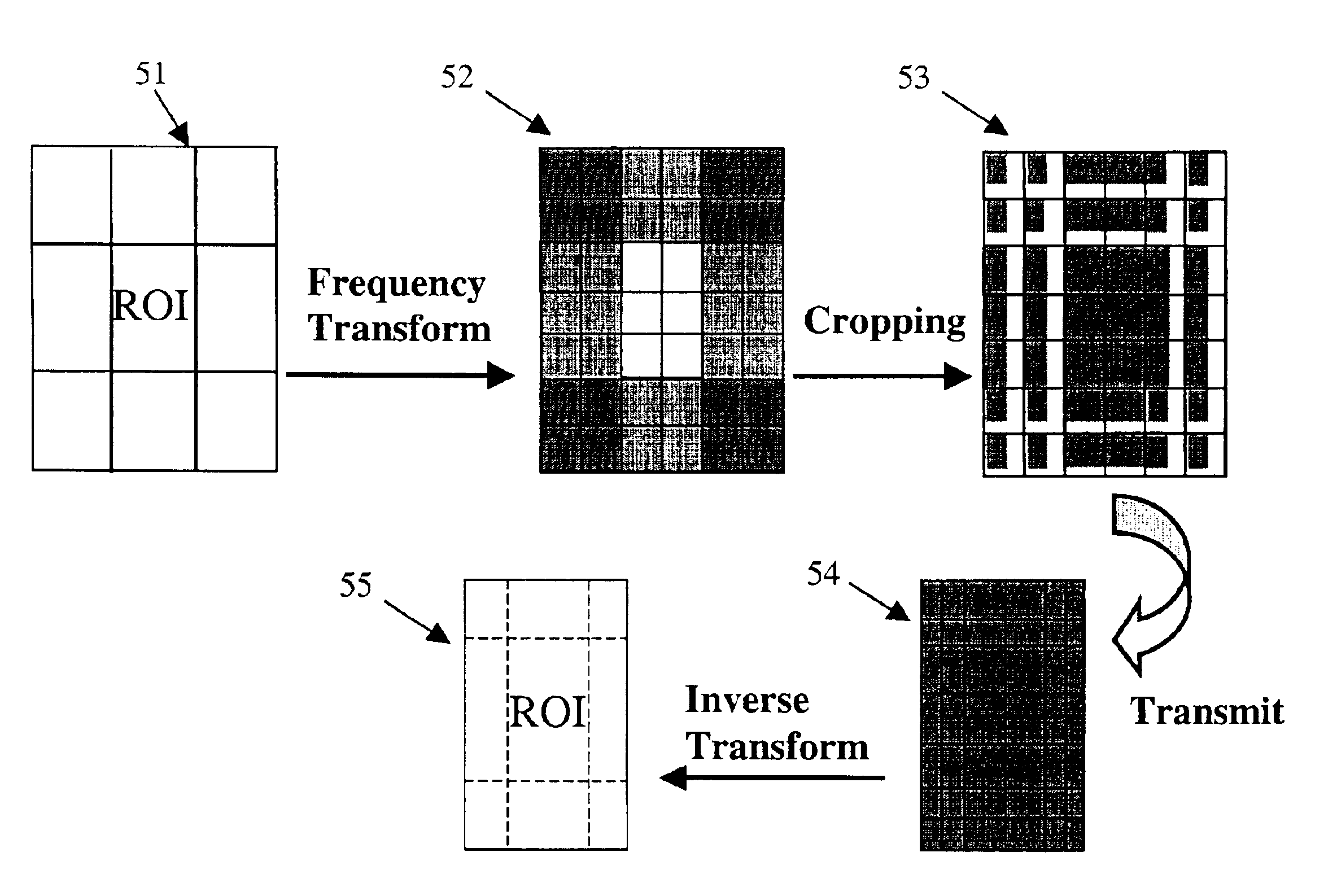
[0008]A system and method of transmission is described for transmitting image data adapted to a first display area size to an apparatus having a smaller second display area size. The system and method of transmission allows a user to view a large image on a hand held device with a small display area by magnifying a region of interest within the large image and de-magnifying peripheral areas about the region of interest, causing, for example, a “fisheye” view of the image to be displayed in the handheld device display area.

Problems solved by technology

One of the main drawbacks that is encountered when using a handheld device to access these types of information sources is that the image data is not adapted to the smaller display area of the handheld device.
In other words, the image does not “fit” within the handheld device's smaller display area.
This partial viewing of the image can be confusing and frustrating to the user since it can become unclear where in the image the user is viewing, thereby making navigation through the image difficult.
However, this technique often makes it difficult or impossible to view image details depending on the size of the display area.
The problem with this method is that it requires the transmission of all frequency coefficients and hence, requires a large amount of bandwidth.
The disadvantage of the method shown in FIG. 1A is that whenever remotely accessing image sources with a handheld device the image data is often wirelessly transmitted over a communication path having a finite bandwidth.
A small or overburdened communication path can significantly hinder the users ability to quickly access remote information by limiting the amount of data that can be transmitted between the information source and the handheld device.
However, transmitting all frequency coefficients tends to consume a relatively large amount of bandwidth that can potentially result in slow remote access times or an inability to remotely access certain image data.

Method used


Image

  • Image transmission for low bandwidth with region of interest
  • Image transmission for low bandwidth with region of interest
  • Image transmission for low bandwidth with region of interest

Examples


Embodiment Construction

[0025]In general, the system and method of the present invention is a technique of transmitting an image adapted to a first display area size, such as a standard computer screen having a particular pixel-by-pixel resolution, to an apparatus having a smaller display area size by scaling the image in the spatial domain by means of coefficient cropping in the frequency domain. When the cropped coefficients are used to display an image within the second smaller display area, a scaled version of the image is displayed. In a specific embodiment, frequency domain coefficients are cropped such that a region of interest of the image is scaled down less than the remainder of the image when displayed in the second smaller display area. Scaling in this manner provides the user with a readable region of interest and with the remainder of the image scaled down so as to facilitate easy image navigation by the user. Furthermore the system and method is a technique of transmitting image data to the ...


PUM


Abstract

A system and method of transmitting an image adapted to a first display area size, such as a standard computer screen having a particular pixel-by-pixel resolution, to an apparatus having a smaller second display area size by scaling the image through coefficient cropping its frequency domain representation. When the cropped frequency coefficients are used to display an image within the second smaller display area, a scaled version of the image is displayed. In a specific embodiment, frequency domain coefficients are cropped such that a region of interest of the image is scaled down less than the remainder of the image when displayed in the second smaller display area. Scaling in this manner provides the user with a readable region of interest with the remainder of the image scaled down so as to facilitate easy image navigation by the user.

Description

FIELD OF THE INVENTION[0001]The present invention relates to transmitting image data for display on two different display screen areas, and more particularly, this disclosure provides a system and method for transmitting image data for display between two differently sized display areas such that a region of interest is viewable to a user.BACKGROUND OF THE INVENTION[0002]Handheld or portable devices, such as personal digital assistants (PDAs), provide a user the flexibility of remotely accessing information sources such as servers, databases and the internet. They are also used to operate software that was originally designed for desktop machines. For example, many Microsoft desktop applications will run on handheld machines. One of the main drawbacks that is encountered when using a handheld device to access these types of information sources is that the image data is not adapted to the smaller display area of the handheld device. In other words, the image does not “fit” within the...

Claims


Application Information

Patent Timeline
IPC IPC(8): H04N7/24H04N7/26H04N7/30G06F3/14G06F3/153G09G5/00G09G5/36H04N21/258H04N21/2662H04N21/462H04N21/4728H04N21/647
CPCH04N21/25808H04N21/2662H04N21/4621H04N21/4728H04N21/64792H04N19/36H04N19/63H04N19/132H04N19/18H04N19/17H04N19/59H04N19/176H04N21/234345H04N21/234363H04N21/25825H04N21/4126H04N21/41407H04N21/440245H04N21/440272
Inventor SILVERSTEIN, D. AMNONCHEN, MEIMUKHERJEE, DEBARGHASAID, AMIRRAY, NIRMALYA
Owner HEWLETT PACKARD DEV CO LP
Learn More