
Remotely actuated, circuit testing emergency stop apparatus and method

a circuit and emergency stop technology, applied in the direction of relays, emergency protective circuit arrangements, instruments, etc., can solve the problems of inadvertent hot wire, e-stop switch controlling (shutting down) operation during abnormal conditions, and components controlling the device during normal conditions, and can become faulty, inadvertent hot wire, and fuse conta

Inactive Publication Date: 2005-04-19
LAZZARO VINCE J
View PDF8 Cites 17 Cited by
  • Summary
  • Abstract
  • Description
  • Claims
  • Application Information

AI Technical Summary

Benefits of technology

[0009]In one aspect of the present invention, the E-stop switch includes a first relay governing a first control circuit in the E-stop switch and a second relay governing a second control circuit in the E-stop switch. Transferring energization from the first control circuit to the second control circuit, and vice-versa, allows testing of the E-stop switch while maintaining electrical operation of equipment served by the E-stop switch and maintaining manual actuation capability of the E-stop switch to shut down the equipment served by the E-stop switch in an emergency situation.

Problems solved by technology

Components controlling the devices during normal conditions, and the E-stop switches controlling (shutting down) operation during abnormal conditions, can become faulty.
Fault conditions generally result from two causes: 1) a failed switch; and / or 2) an inadvertent hot wire.
A failed switch usually results from a fused contact, often occurring after a rated contact current is exceeded.
Because many power sources are not well regulated, current surges are not uncommon, therefore, fused contacts occasionally occur.
Also, environmental conditions can affect contact surfaces, contributing to contact failure.
If a contact in an E-stop switch, control circuit, or power relay becomes fused, there is often no way to know until the equipment becomes uncontrollable.
Furthermore, an inadvertent (stray) hot wire can short circuit a switch, or provide power to a motor from an inadvertent source by bypassing a switch.
The ability to periodically inspect and / or test switch components, equipment control circuitry, and the E-stop switches, is a very important part of successful preventive maintenance plan, but such inspection / testing is not always possible, or at least not practical.
Although there are no strict standards for the testing of E-stop switches and equipment control circuitry, most are not adequately tested because of the interference testing has with equipment operation.

Method used


Image

  • Remotely actuated, circuit testing emergency stop apparatus and method
  • Remotely actuated, circuit testing emergency stop apparatus and method
  • Remotely actuated, circuit testing emergency stop apparatus and method

Examples


first embodiment

Control Circuitry and Sequence Testing:

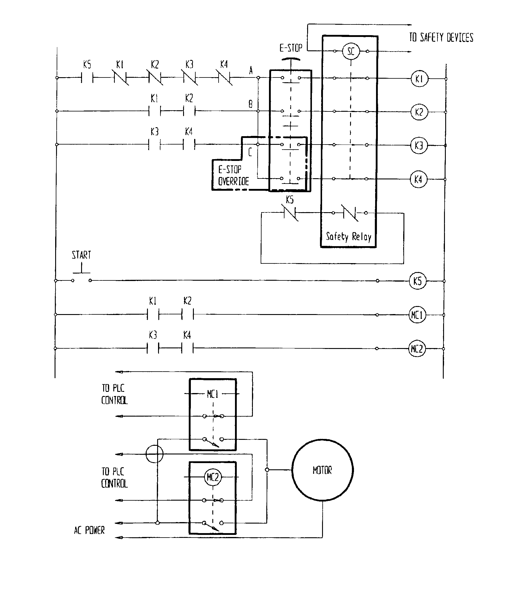
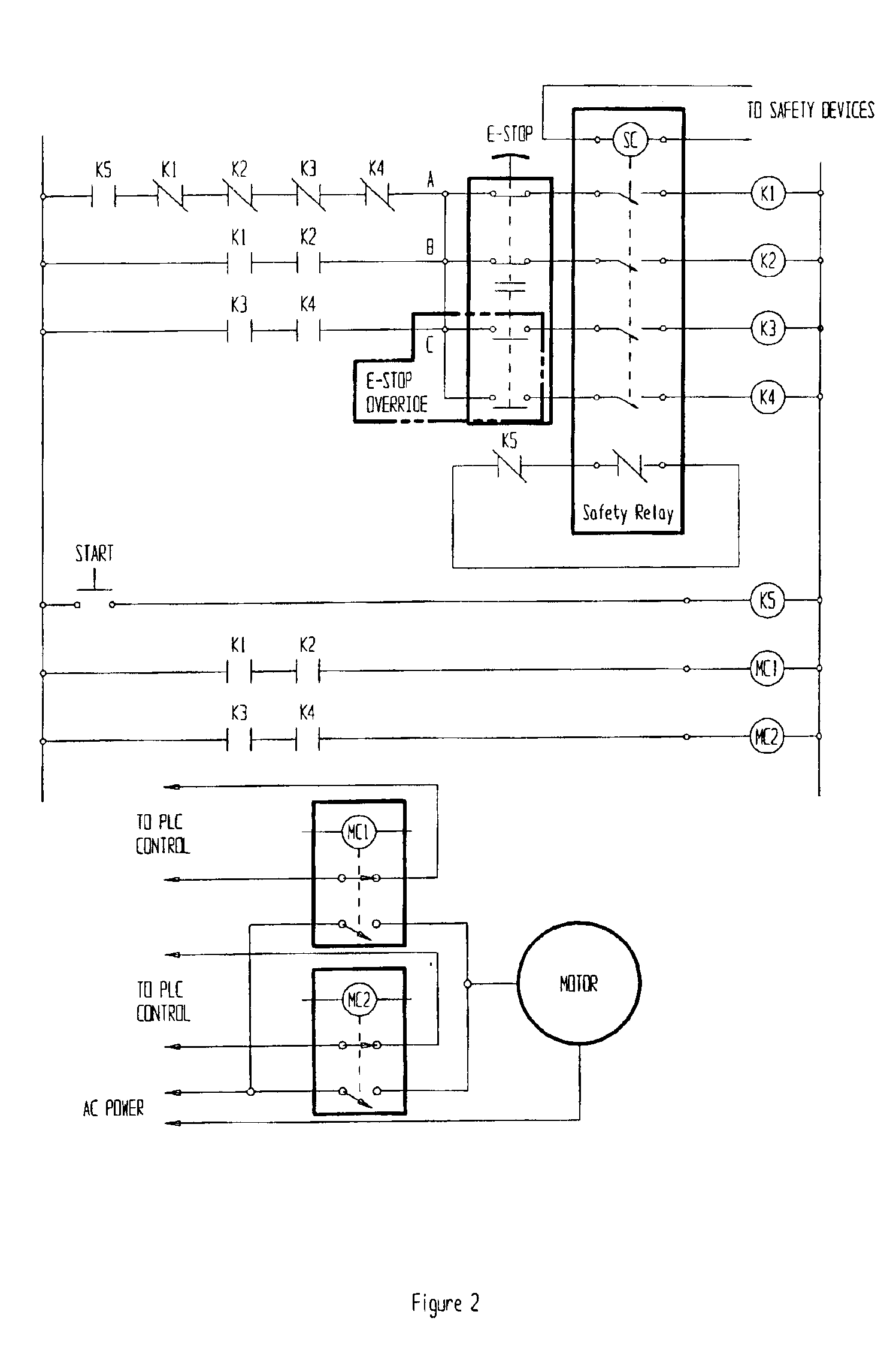
[0052]FIGS. 2 through 11 illustrate an elementary diagram of one embodiment of a control reliable circuit incorporating the E-stop of the present invention into control circuitry serving one or more items of electrical equipment (simply denoted as Motor in FIGS. 2-11).

[0053]The control reliable circuit includes two parallel motor source contactors MC1, MC2, two control circuits, a safety relay and one or more E-stops. The motor could be started by a momentary push button switch (start) and stopped by opening a safety device, including activating the E-stop. The E-stop relays, and associated control circuits, are energized and de-energized in a timed sequence by a PLC. The first E-stop relay could govern a primary control circuit operating the first motor source contactor MC1, while the second E-stop relay could be considered the E-stop override relay and govern a secondary control circuit operating the second motor source contactor MC2.

[0054]On...

second embodiment

Control Circuitry with Similar Sequence Testing:

[0080]Similar to the first control circuit embodiment, a typical application for the second control circuit embodiment, using either E-stop switch of the present invention, could be a dual safety reliable circuit, as shown in FIG. 16, controlling a single motor, or a plurality of motors and / or equipment, running twenty-four hours per day, seven days per week. In this embodiment (described using component numbers of the second E-stop switch 60), the motor safety circuits can again be checked without shutting off power to the motor or equipment.

[0081]The first (primary) contact block 66 could control one safety or control circuit, while another safety or control circuit is controlled by the secondary (override) contact block 76. A PLC could control the primary and the secondary shaft solenoids 72, 78 of the E-stop switch 60. A normally closed captive contact in each of two motor control contactors (one motor control contactor controlled ...

third embodiment

Control Circuitry Carrying out a Second Sequence Testing Technique

[0082]FIGS. 17 through 21 illustrate a second method for testing the E-stop switches and control circuitry of the present invention. Here, a supervised, solenoid actuated E-stop switch can be tested during every machine stop and / or start sequence.

[0083]FIG. 17 shows the E-stop switch and control logic prior to a cold motor (equipment) start up. The primary contacts of the E-stop are normally closed and the secondary (override) contacts are normally open. The motor control relay MCR is not energized, so the motor is not running.

[0084]FIG. 18 shows the E-stop switch and control logic with the start button depressed. The MCR is now energized, closing the contacts of the MCR. This creates a latching circuit. The MCR will now remain on after the start button is released. The motor is now running.

[0085]FIG. 19 shows the E-stop switch and control logic with the E-stop activated. This deactivates the MCR, removing power to th...


PUM


Abstract

The present invention is a remotely actuated emergency stop (E-stop) switch, with equipment control circuitry, providing a method for testing the E-stop switch and control circuitry to assure circuit and switch integrity, anytime, without equipment operational interruption, and without negating the manual actuation function of the E-stop switch to immediately cut all power to the equipment. The E-stop switch includes a first relay governing a first control circuit and a second relay governing a second control circuit. Each control circuit governs a motor source control contactor, which, when closed, provides power to the equipment. Transferring energization, and motor control, from the first control circuit to the second control circuit, and vice-versa, allows testing, in turn, of the de-energized components of the E-stop switch and control circuitry while the equipment remains operational. Remote actuation and circuit monitoring and testing is controlled by a Program Logic Controller (PLC).

Description

RELATED INVENTIONS[0001]This application claims priority under 35 U.S.C. § 119 (e) to U.S. Provisional Patent Application Ser. No. 60 / 284,793, filed Apr. 19, 2001, entitled “A Remotely Actuated, Circuit Testing Emergency Stop Apparatus and Method.”FIELD OF THE INVENTION[0002]The present invention relates generally to emergency stop switches and equipment control circuitry, and more particularly to a method and apparatus for testing equipment control circuitry and emergency stop switches while equipment is operating, without sacrificing emergency stop switch functionality.BACKGROUND OF THE INVENTION[0003]Many devices require electrical power to operate, and controlling the devices during normal conditions, while providing for safety during abnormal conditions, is integral to proper device operation. For example, a typical factory often includes many machines (motors), linked together in operation, and linked to other devices, for handling items to be assembled and for handling tools ...

Claims


Application Information

Patent Timeline
IPC IPC(8): H01H47/00
CPCH01H47/002
Inventor LAZZARO, VINCE J
Owner LAZZARO VINCE J
Learn More