Miniature device with bossed suspension member

Inactive Publication Date: 2005-04-19
COHERENT INC
View PDF6 Cites 4 Cited by
  • Summary
  • Abstract
  • Description
  • Claims
  • Application Information

AI Technical Summary

Benefits of technology

[0004]Miniature devices, such as micromechanical or micromachined devices, having movable members supported above a substrate by one or more suspension members have been disclosed. See, for example, U.S. Pat. No. 5,998,

Problems solved by technology

Unfortunately, the features described therein do not have adequate side-stiffness for increased deflection.
Unfortunately, notched flexures are quite stiff due to the limited amount of material subject to bending in the notch region.
Additionally, since all of the strain in the flexure is localized, the maximum angular deflection of such a flexure is limited by the maximum strain which the material can tolerate without failure.
The difficulty in maintaining the required width tolerance of the hinge during the fabrication of these devices has additionally made them expensive to manufacture and limited their use.

Method used


Image

  • Miniature device with bossed suspension member
  • Miniature device with bossed suspension member
  • Miniature device with bossed suspension member

Examples


Embodiment Construction

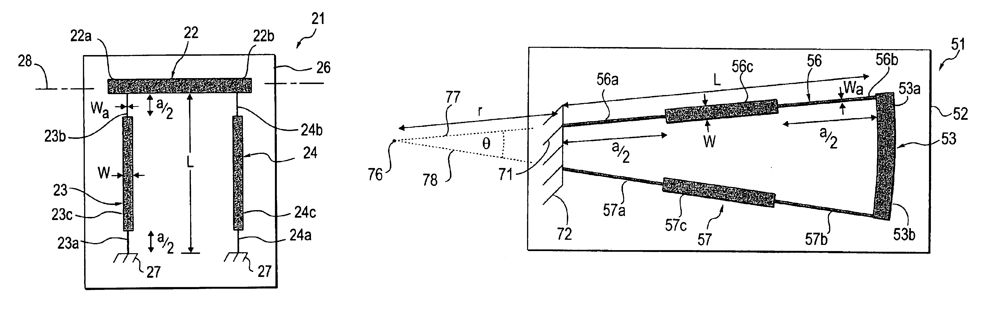
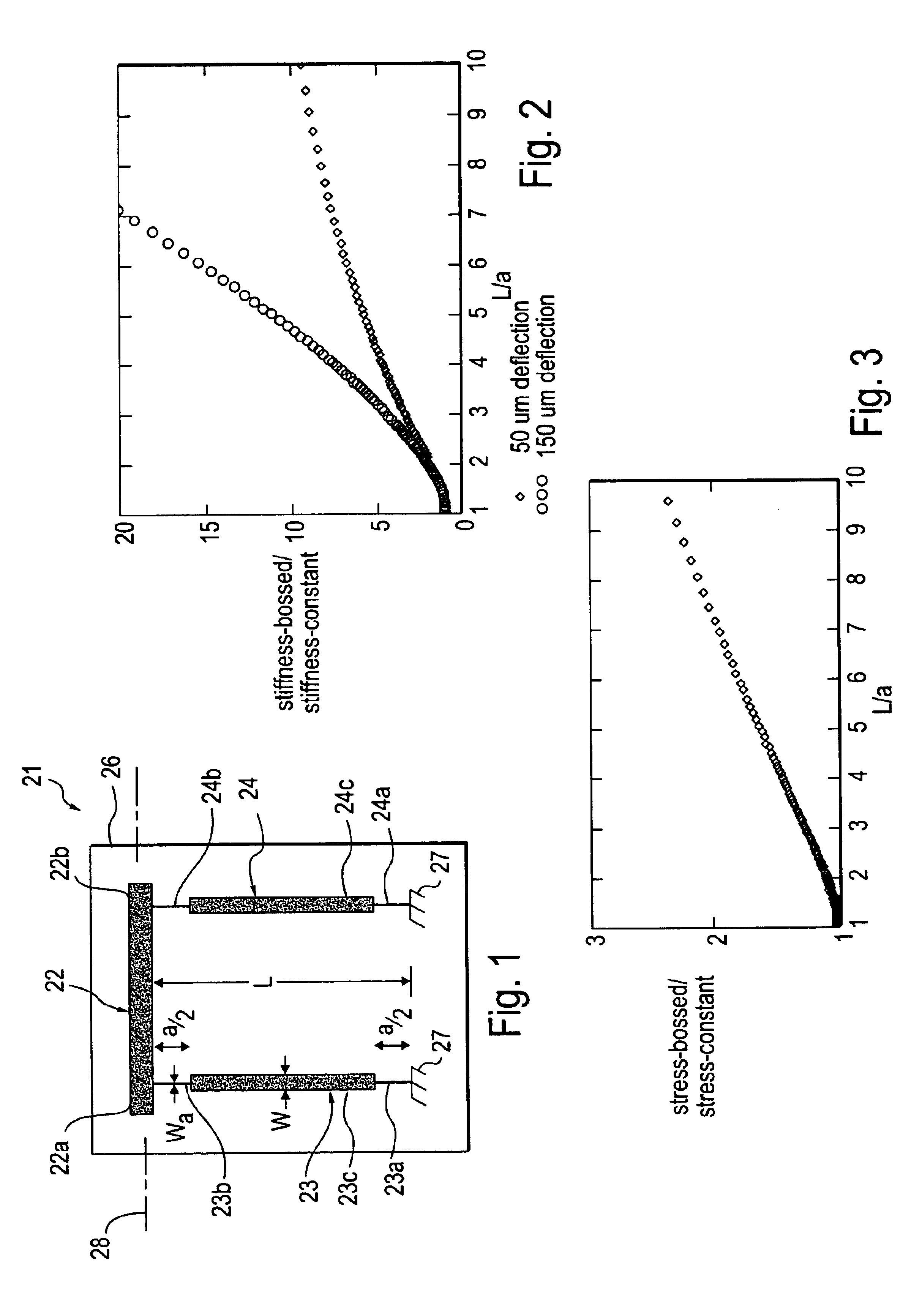
[0023]One embodiment of the miniature device with bossed suspension member of the present invention is shown schematically in FIG. 1. Miniature device 21 shown therein includes a movable or translatable member 22 and first and second suspension members 23 and 24 overlying a substrate 26. Miniature device 2 can be part of an actuator, sensor, accelerometer or any other device having a movable member suspended over a substrate. One miniature device having such a movable member is disclosed in U.S. Pat. No. 5,998,906, wherein a micromachined linear electrostatic actuator having a translatable member disclosed. Another exemplary miniature device having such a movable member is disclosed in U.S. patent application Ser. No. 09 / 547,698 filed Apr. 12, 2000, now U.S. Pat. No. 6,384,510, the entire content of which is incorporated herein by this reference.

[0024]Substrate 26 is made for any suitable material such as silicon and is preferably formed from a silicon wafer. The substrate can be of...


PUM


Abstract

A miniature device comprising a substrate, a movable member overlying the substrate and first and second spaced-apart suspension members. Each of the first and second suspension members has a first bendable end portion coupled to the substrate and a second bendable end portion coupled to the movable member and a substantially rigid central portion. The first and second end portions of each suspension member have respective first and second lengths and the suspension member has an overall length. The sum of the first and second lengths of each suspension member ranges from 5% to 40% of the overall length of the suspension member.

Description

CROSS-REFERENCE TO RELATED APPLICATION[0001]The application claims priority to U.S. provisional patent application Ser. No. 60 / 275,957 filed Mar. 14, 2001, the entire content of which is incorporated herein by this reference.FIELD OF THE INVENTION[0002]The present invention relates generally to miniature devices and more particularly to miniature devices having suspension members.BACKGROUND[0003]A summary of traditional electrostatic microactuator design techniques is given by Legtenberg, Groeneveld and Elwenspoek in their paper “Comb-drive actuators for large displacements”, J. Micromech. Microeng., 1996. Unfortunately, the features described therein do not have adequate side-stiffness for increased deflection.[0004]Miniature devices, such as micromechanical or micromachined devices, having movable members supported above a substrate by one or more suspension members have been disclosed. See, for example, U.S. Pat. No. 5,998,906 which discloses a linear microactuator for translatin...

Claims


Application Information

Patent Timeline
IPC IPC(8): H02N1/00B81B3/00
CPCH02N1/008
Inventor JERMAN, JOHN H.GRADE, JOHN D.
Owner COHERENT INC
Why Eureka
Try Eureka