
Energy storage flywheel system with a power connector that integrally mounts one or more controller circuits

a technology of energy storage and flywheel, which is applied in the field of electrical power generation and storage systems, can solve the problems of unwanted source of weight, time-consuming and costly instances, and achieve the effect of reducing power cable length and alleviating the need for conducting time-consuming electrical connections

Inactive Publication Date: 2005-04-19
HONEYWELL INT INC
View PDF16 Cites 38 Cited by
  • Summary
  • Abstract
  • Description
  • Claims
  • Application Information

AI Technical Summary

Benefits of technology

[0006]The present invention provides power connector and circuit board configuration that allows at least a motor/generator controller circuit to be mounted on the housing of an energy storage flywhee

Problems solved by technology

Power cables can be a source of unwanted electromagnetic interference (EMI) to some circuit components, and can also be an unwanted source of weight.
Moreover, the power cables may then need to be electrically coupled to the controller, which can in some instances be time consuming and costly.

Method used


Image

  • Energy storage flywheel system with a power connector that integrally mounts one or more controller circuits
  • Energy storage flywheel system with a power connector that integrally mounts one or more controller circuits
  • Energy storage flywheel system with a power connector that integrally mounts one or more controller circuits

Examples


Embodiment Construction

[0020]Before proceeding with a detailed description, it is to be appreciated that the described embodiment is not limited to use in conjunction with a spacecraft. Thus, although the present embodiment is, for convenience of explanation, depicted and described as being implemented in an energy storage flywheel system in a satellite, it will be appreciated that it can be implemented in others systems and environments, both terrestrial and extraterrestrial including, for example, land-based power systems and power systems on sea-going vessels such as surface ships and submarines.

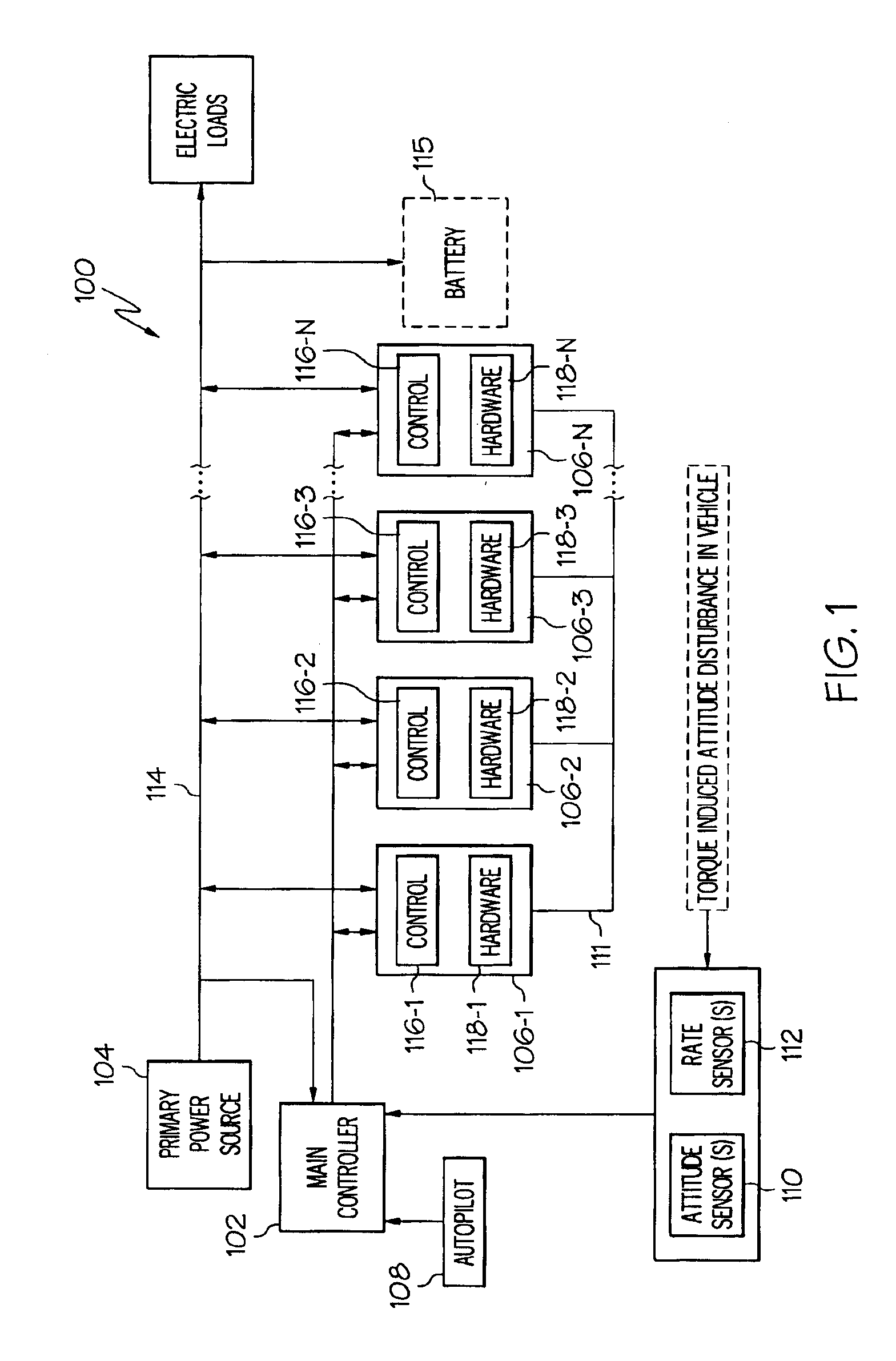
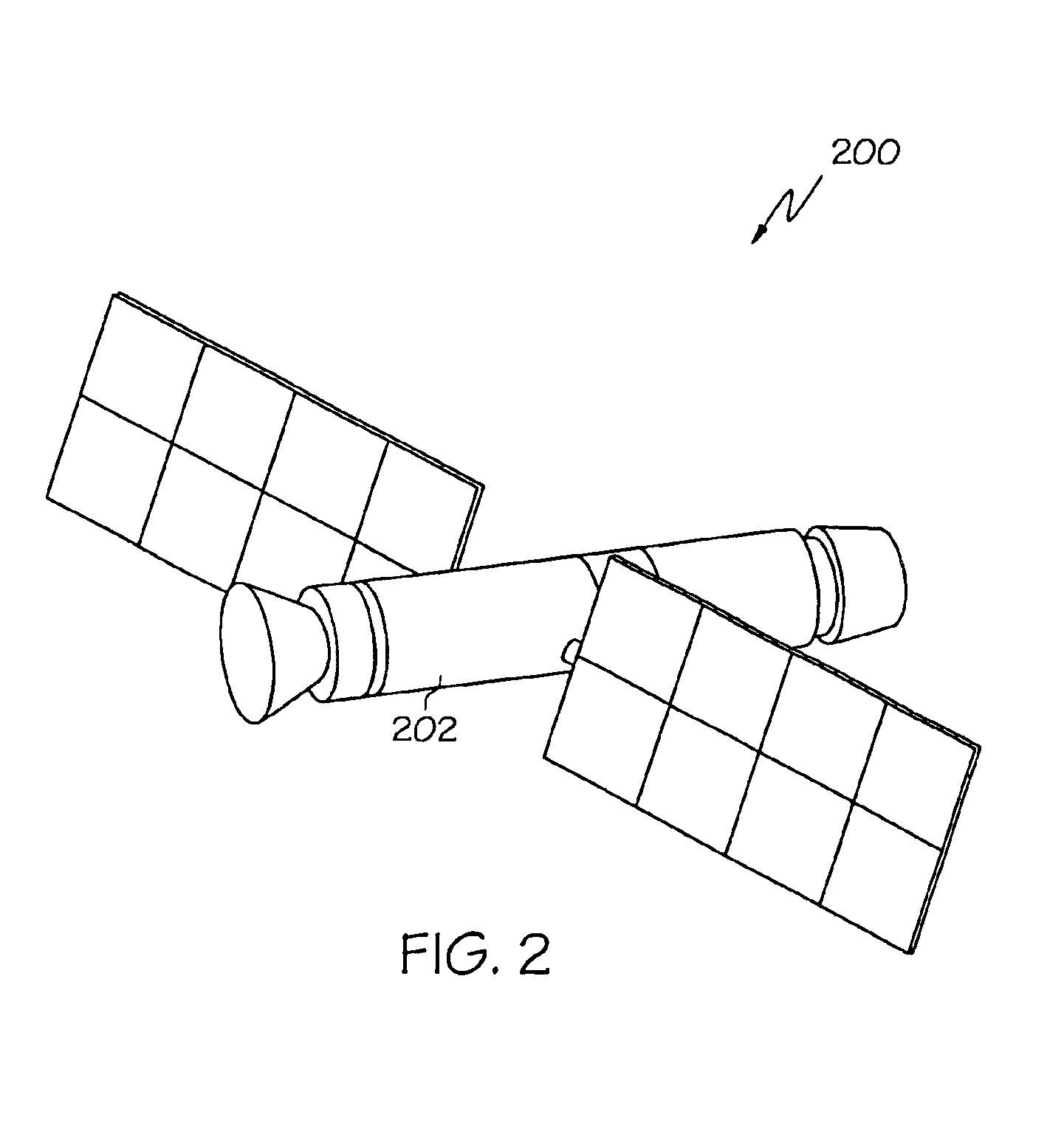
[0021]Turning now to the description and with reference first to FIG. 1, a functional block diagram of an exemplary power and attitude control system 100 for a spacecraft is shown. The system 100 includes a main controller 102, a primary power source 104, and a plurality of flywheel systems 106 (106-1, 106-2, 106-3, . . . 106-N). A perspective view of an exemplary physical embodiment of a spacecraft 200 that ma...


PUM


Abstract

An energy storage flywheel system that includes a power connector extending through the flywheel housing assembly and is hermetically sealed thereto. A circuit board, on which is mounted at least a motor / controller circuit, is coupled to the power connector adjacent to the flywheel housing assembly.

Description

FIELD OF THE INVENTION[0001]The present invention relates to electrical power generation systems and, more particularly, to a system of electrical power generation and storage that has one or more flywheels and that can be used in space, vehicle, or terrestrial applications.BACKGROUND OF THE INVENTION[0002]Many satellites and other space vehicles, as well as some terrestrial vehicle applications, such as seagoing vessels, include a main source of electrical power and a standby, or backup, source of electrical power. The main source of electrical power may include one or more photovoltaic arrays, in the case of a satellite, or one or more engine-driven or turbine-driven generators, in the case of seagoing vessels. The standby electrical power source may include a battery, and may additionally include one or more energy storage flywheels, and / or one or more separate engine-driven or turbine-driven generators.[0003]In systems that include one or more energy storage flywheels, the energ...

Claims


Application Information

Patent Timeline
IPC IPC(8): F16F15/315F16F15/30H02K7/02H02K7/00H02K11/04H02K5/22
CPCF16F15/315H02K5/225H02K11/048H02K7/025Y02E60/16H02K7/02
Inventor WINGETT, PAUL T.POTTER, CALVIN C.GILES, TODD R.
Owner HONEYWELL INT INC
Learn More