
Roadway-powered electric vehicle system having automatic guidance and demand-based dispatch features

Inactive Publication Date: 2005-04-12
H R ROSS IND
View PDF9 Cites 117 Cited by
  • Summary
  • Abstract
  • Description
  • Claims
  • Application Information

AI Technical Summary

Benefits of technology

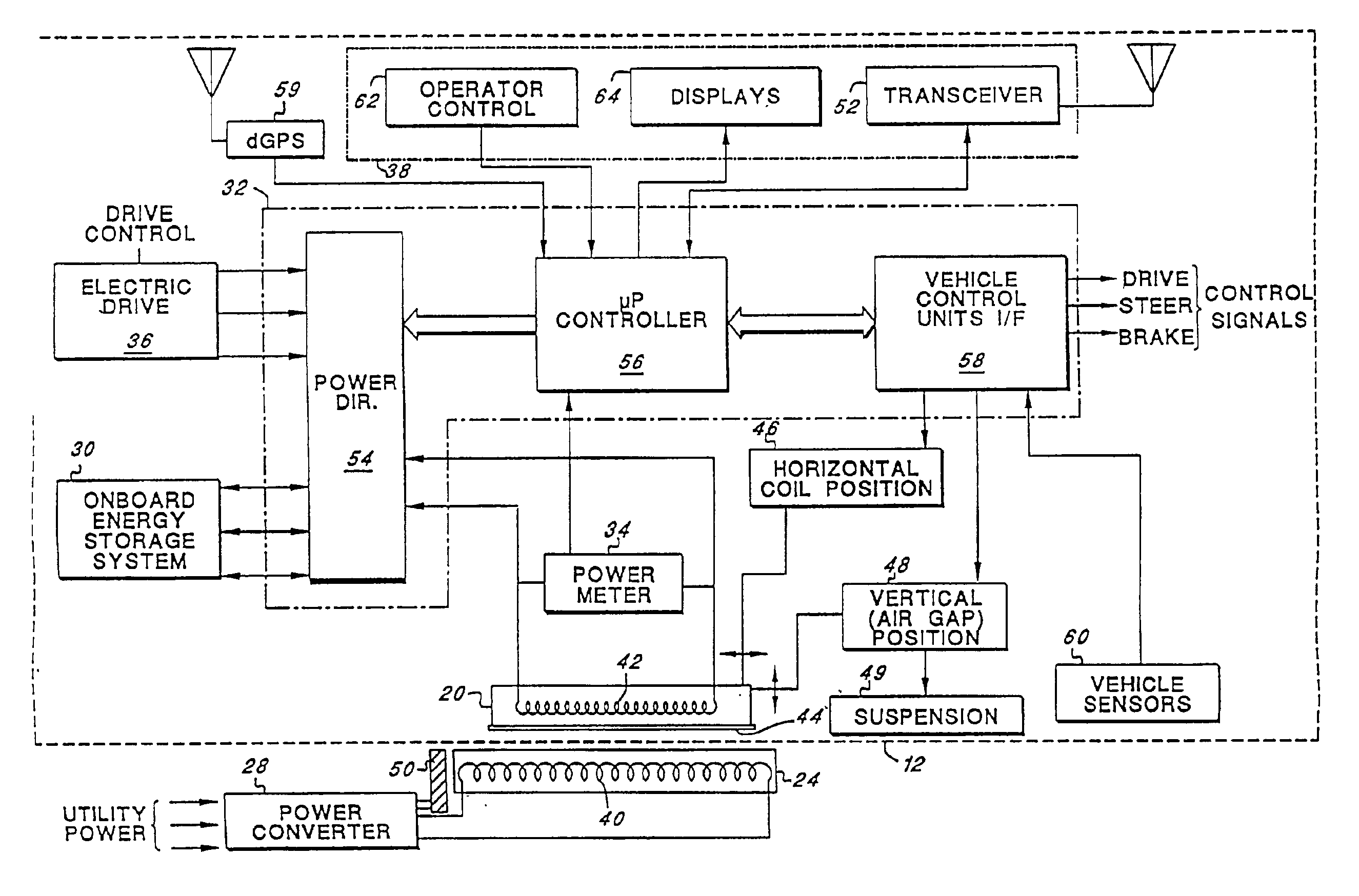
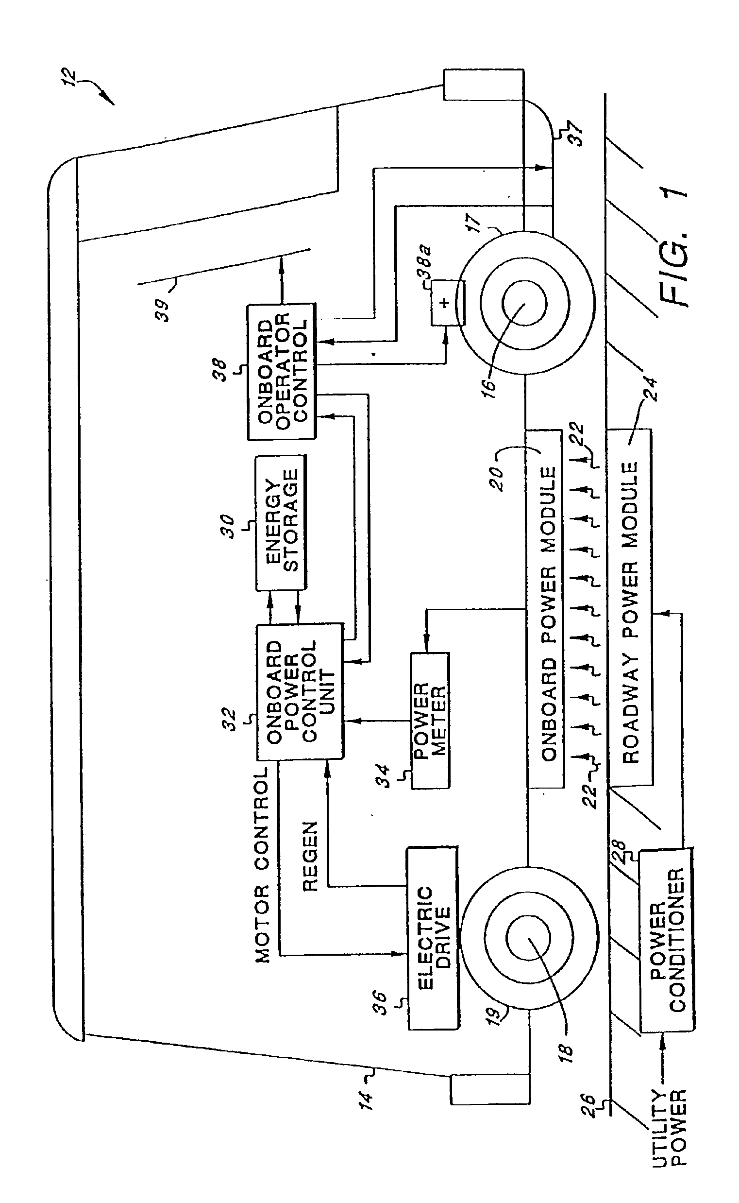
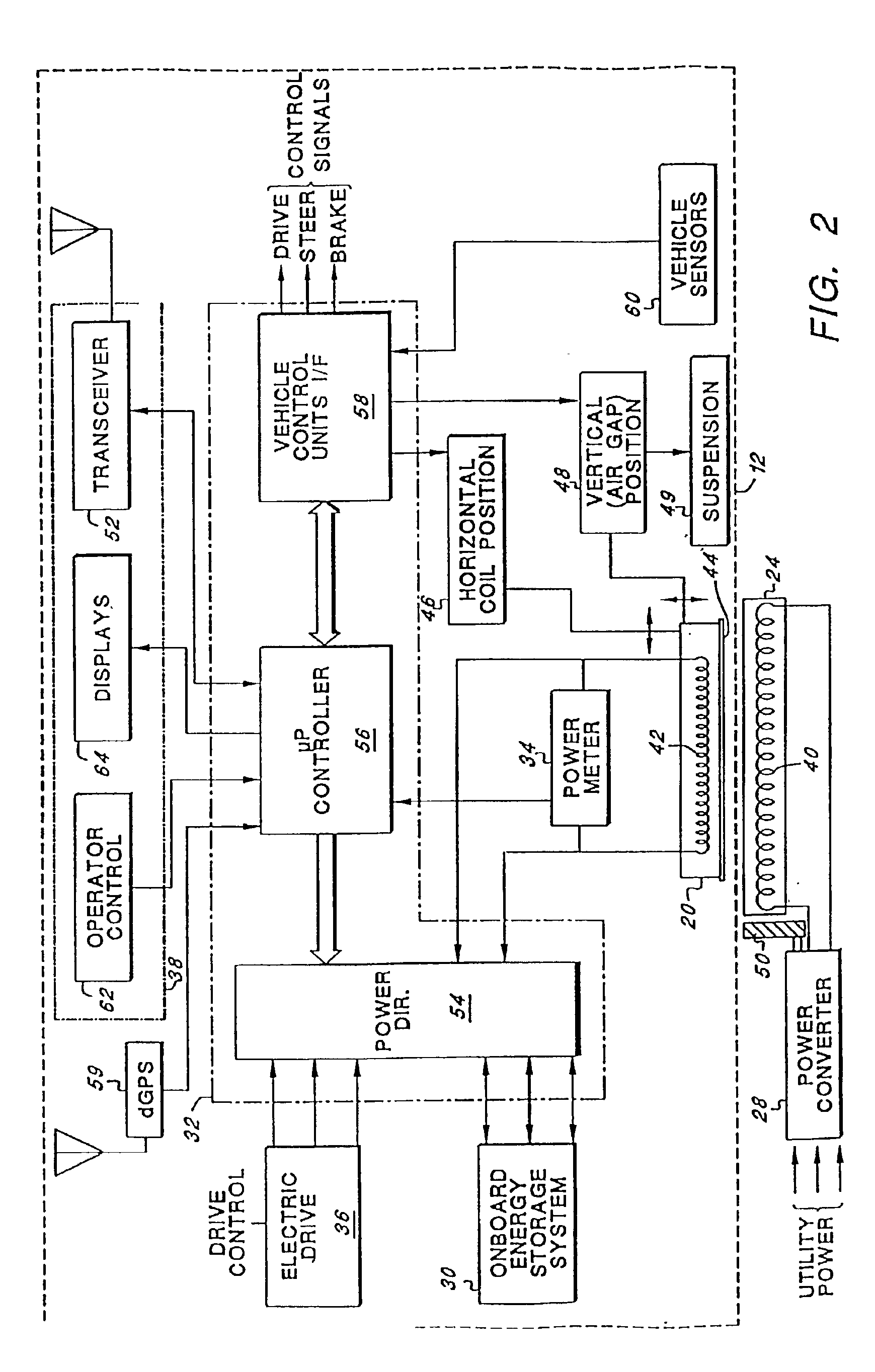
The present invention addresses the above and other needs by providing an improved roadway-powered electric vehicle system that includes: (1) an all-electric vehicle; and (2) a roadway network over which the vehicle travels. The all-electric vehicle includes one or more onboard energy storage elements or devices that can be rapidly charged or energized with energy obtained from an electrical current. The vehicle further includes an on-board power controller that extracts energy from the energy storage elements, as needed, and converts such extracted energy to electrical energy used to propel the electric vehicle. Advantageously, the energy storage elements of the vehicle may be charged while the vehicle is in operation. Such charging occurs, e.g., through a network of power coupling elements embedded in the roadway. As the vehicle passes over such power coupling elements, as it traverses the roadway network, electrical current is coupled to the electric vehicle, which electrical current is then used to charge the energy storage devices. Advantageously, such power coupling elements may be coils embedded at strategic locations in existing roadways and highways. Such embedding can be done at a very modest cost.

Problems solved by technology

In contrast, vehicles that rely upon an internal combustion engine (ICE), in whole or in part, for their power source are continually fouling the air with their exhaust emissions.
However, such systems typically require their own highly specialized roadway, or right-of-way, system, as well as the need for an electrical energy source, such as a continuously electrified rail or overhead wire, with which the EV remains in constant contact.
These requirements make such systems extremely expensive to acquire, build and maintain.
Moreover, such externally-powered EV systems are not able to provide the convenience and range of the ICE automobile (which effectively allows its operator to drive any where there is a reasonable road on which the ICE vehicle can travel).
Unfortunately, however, such rechargeable battery-driven EV's have not yet proven to be economically viable nor practical.
For most vehicle applications, such rechargeable battery-driven EV's have not been able to store sufficient electrical energy to provide the vehicle with adequate range before needing to be recharged, and / or to allow the vehicle to travel at safe highway speeds for a sufficiently long period of time.
Disadvantageously, the energy density (i.e., the amount of energy that can be stored per unit volume) of currently-existing electrochemical batteries has been inadequate.
That is, when sufficient electrical storage capacity is provided on board the vehicle to provide adequate range, the number of batteries required to provide such storage capacity is prohibitively large, both in volume and weight.
Moreover, when such batteries need to be recharged, the time required to fully recharge the batteries is usually a number of hours, not minutes as most vehicle operators are accustomed to when they stop to refill their ICE vehicles with fuel.
Further, most currently-existing electrochemical batteries are not suited for numerous, repeated recharges, because such batteries, after a nominal number of recharges, must be replaced with new batteries, thereby significantly adding to the expense of operating the rechargeable battery-driven EV.
Disadvantageously, however, the use of such mechanical flywheel significantly complicates the drive system of the vehicle, and also significantly adds to the weight of the vehicle, thereby limiting its useful range between charges.
Further, the mechanical flywheel operating at fast speeds may present a safety hazard.

Method used


Image

  • Roadway-powered electric vehicle system having automatic guidance and demand-based dispatch features
  • Roadway-powered electric vehicle system having automatic guidance and demand-based dispatch features
  • Roadway-powered electric vehicle system having automatic guidance and demand-based dispatch features

Examples


Embodiment Construction

The following description is of the best mode presently contemplated for carrying out the invention. This description is not to be taken in a limiting sense, but is made merely for the purpose of describing the general principles of the invention. The scope of the invention should be determined with reference to the claims.

Broadly stated, the invention relates to a roadway-powered electric vehicle system that includes a network of highways and roadways that have been electrified at select locations, and a fleet of roadway-powered electric vehicles (RPEV's) that traverse the network of highways and roadways and receive their electrical operating power from the electrified highways and roadways. Many of the components that make up the RPEV system of the embodiments described herein are components that already exist and have been used for other types of EV systems, or other applications. Such components may be found, for example, and are described in the following documents, all of whi...


PUM


Abstract

A roadway-powered electric vehicle system includes an all-electric vehicle and a roadway network over which the vehicle travels. The vehicle has one or more onboard energy storage elements or devices that can be rapidly charged or energized with energy obtained from an electrical current, such as a network of electromechanical batteries. The electric vehicle further includes an on-board controller that extracts energy from the energy storage elements, as needed, and converts such extracted energy to electrical power used to propel the electric vehicle. The energy storage elements may be charged while the vehicle is in operation.

Description

BACKGROUND OF THE INVENTIONThe present invention relates to electric vehicles, and more particularly to an all-electric vehicle system that is powered from an onboard high-specific-power energy storage device, and that receives power to charge the energy-storage device inductively through coils in the roadway over which the vehicle travels. The invention further relates to enhancements included within such a roadway-powered electric vehicle system, such as an automatic position-determining system, automated vehicle guidance, demand-based vehicle dispatch, and the like.In recent years, there has been an increasing emphasis on the development of an all electric vehicle (EV) or other zero emission vehicle (ZEV). The goal, as mandated by many governmental jurisdictions, is to have a certain percentage of all vehicles be zero-emission vehicles. Advantageously, zero-emission vehicles do not directly emit any exhaust or other gases into the air, and thus do no pollute the atmosphere. In co...

Claims


Application Information

Patent Timeline
IPC IPC(8): B60L11/00B60L5/00B60L11/16B60L50/30G01S19/48
CPCB60L5/005B60L11/16B60L11/1803B60L11/182B60L11/1831B60L7/14Y02T90/121B60L2210/20B60L2230/16B60L2250/16B60L2270/32B60L2270/36Y02T10/7005Y02T10/7033Y02T10/7088Y02T10/725Y02T90/122Y02T90/127Y02T90/128Y02T90/14Y02T90/16Y02T90/163Y02T90/125B60L2200/26Y02T10/7027B60L50/30B60L50/51B60L53/124B60L53/126B60L53/305B60L53/39Y02T10/70Y02T10/7072Y02T10/72Y02T90/12
Inventor ROSS, HOWARD R.
Owner H R ROSS IND
Learn More