
Process of manufacturing a breathing bag and breathing bag manufactured by such process

a manufacturing process and breathing bag technology, applied in the field of manufacturing a breathing bag and a breathing bag manufactured, can solve the problems of insufficient stiff or rigid connection of the connector portion, the inability to connect, and the process is typically slow

Inactive Publication Date: 2005-04-12
SUNMED GRP HLDG LLC
View PDF3 Cites 26 Cited by
  • Summary
  • Abstract
  • Description
  • Claims
  • Application Information

AI Technical Summary

Benefits of technology

"The patent describes a process for making a breathing bag with a connector and a distensible portion. The process involves using moldable material that is formed into the connector and distensible portions using compression molding and blow molding or vacuum molding. The two parts are formed integrally. The technical effect of this process is the creation of a breathing bag that is easy to manufacture and use."

Problems solved by technology

Such process is typically slow, unwantedly expensive and lends itself to imperfections.
Further, the typical prior art breathing bag is made by the aforenoted dipping process and has a relatively thin wall thickness such that the connector portion is insufficiently stiff or rigid to connect, for example, to a standard 22 mm tapered male fitting or a non-tapered tubular or hollow cylindrical fitting.
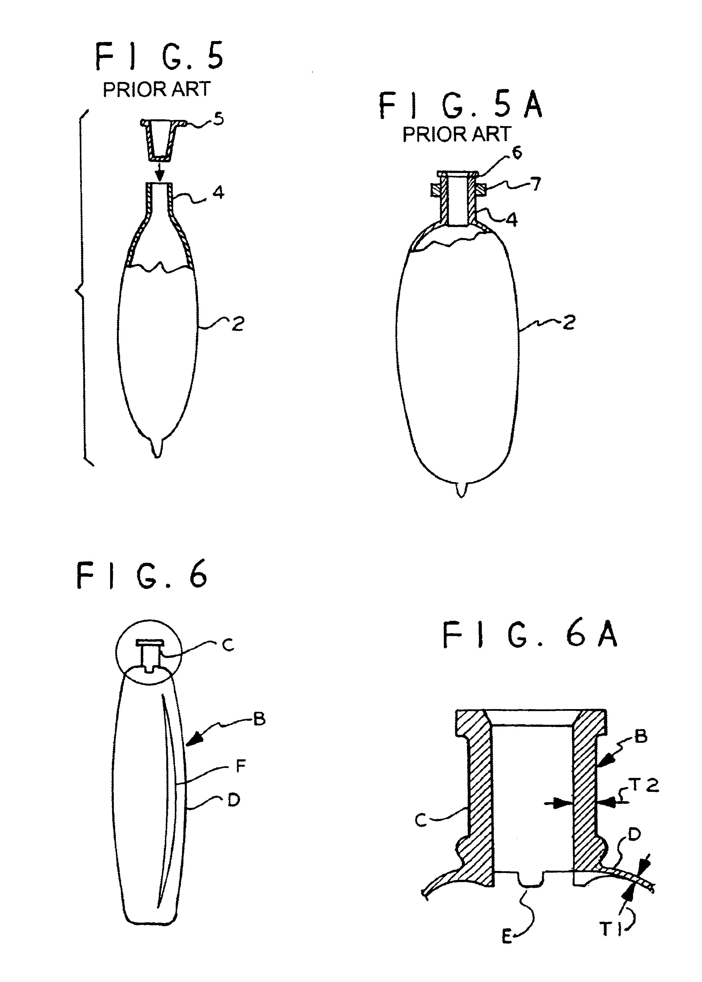
Such thickness means that the neck portions 4 are insufficiently stiff or rigid to be connected directly to one of the above-noted male fittings.
As is further known to the art, the requirement of these additional bushings, the retaining bands, and the manufacturing steps required to insert and retain the bushings in the breathing bags further add unwanted cost and expense to the manufacture of the typical prior art breathing bag.

Method used


Image

  • Process of manufacturing a breathing bag and breathing bag manufactured by such process
  • Process of manufacturing a breathing bag and breathing bag manufactured by such process
  • Process of manufacturing a breathing bag and breathing bag manufactured by such process

Examples


Embodiment Construction

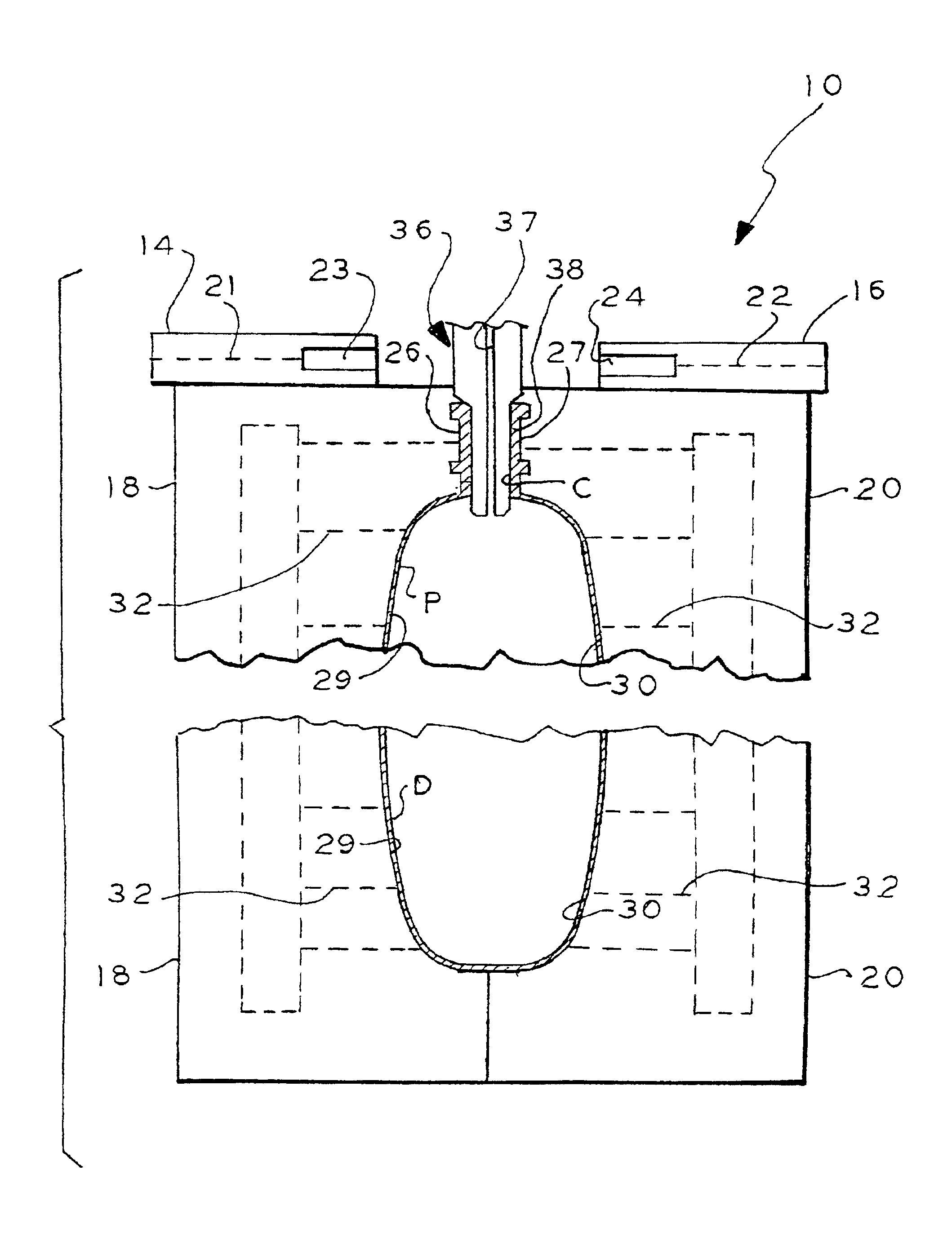
A breathing bag embodying the present invention is illustrated diagrammatically in FIGS. 6 and 6A and indicated by alphabetical designation B. Breathing bag B includes a connector portion C and a distensible portion D. The connector portion C is typically sized to connect directly to an ISO 22 mm male fitting and the distensible bag D expands and contracts in the process of delivering, or assisting in delivering, gas to the patient as noted above. As will be better understood from FIG. 6A, the connector portion C has a greater thickness than the thickness of the distensible portion D; the greater thickness of the connector portion C provides it with the strength or rigidity to serve its above-noted connector function. For illustration the thickness of the connector portion C has been exaggerated with respect to the thickness of the distensible portion D in FIG. 6A. In one embodiment, the distensible portion D had a thickness T1 of about 0.015-0.020 inch and the neck portion C had a ...


PUM

PropertyMeasurementUnit
thicknessaaaaaaaaaa
thickness T2aaaaaaaaaa
thicknessaaaaaaaaaa

Abstract

Process for manufacturing a breathing bag including a connector portion and a distensible portion including the steps of providing moldable material, forming a portion of the moldable material into the connector portion of the breathing bag and forming another portion of the moldable material into the distensible portion of the breathing bag. The moldable material may be provided by extruding a parison of thermoplastic material; the connector portion of the breathing bag may be formed by compression molding and the distensible portion of the breathing bag may be formed by blow molding or blow and vacuum molding; such distensible portion and connector portions are formed or molded integrally. A breathing bag made by such process.

Description

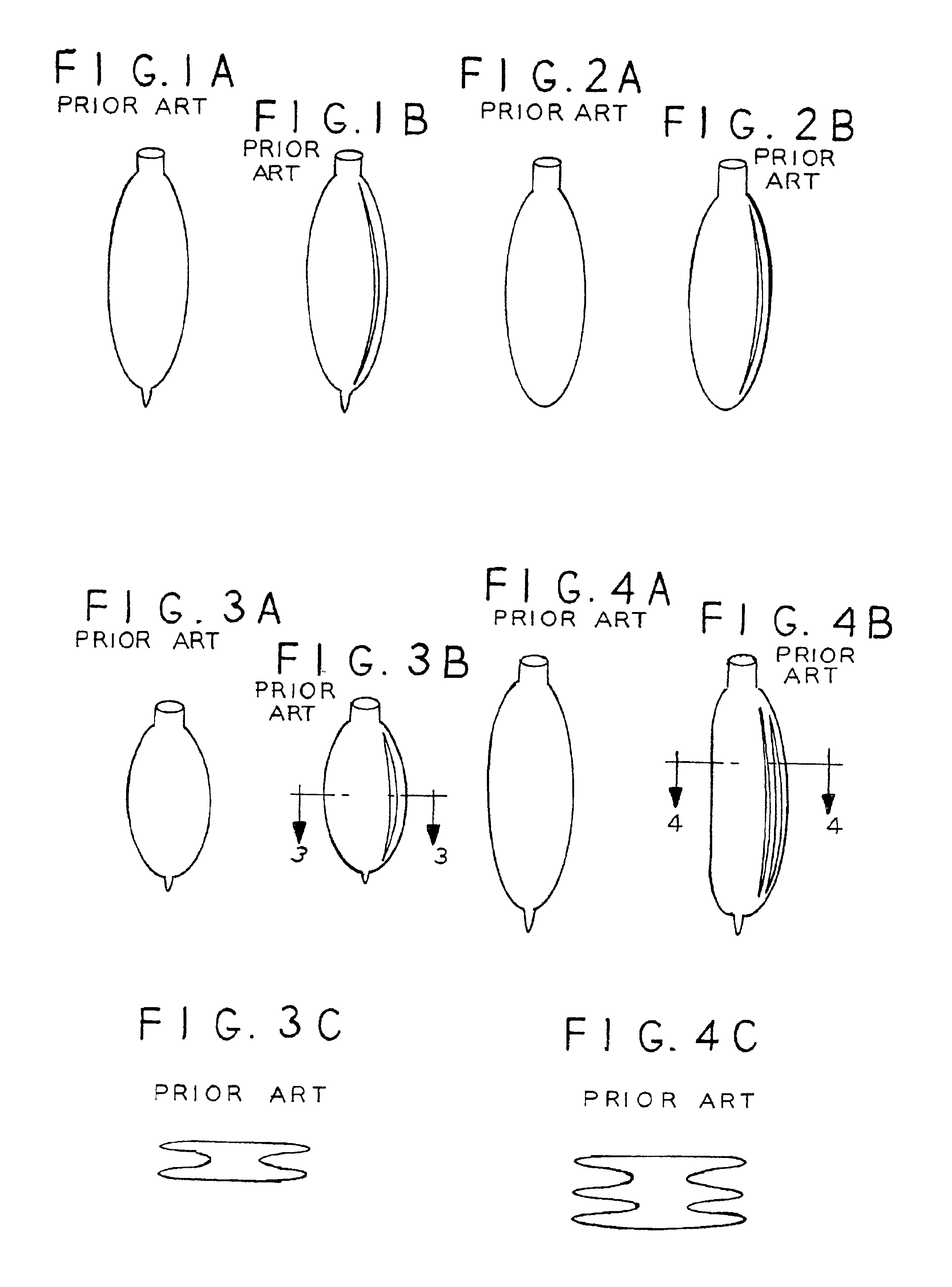
BACKGROUND OF THE INVENTIONThis invention relates to a process of manufacturing a breathing bag and to a breathing bag manufactured by such process.Breathing bags are well known to the medical arts for delivering, or assisting in delivering, gas to a patient such as anesthesia gas or a breathing gas such as oxygen or oxygen-enriched air. Typical prior art breathing bags are illustrated diagrammatically in FIGS. 1A and 1B, FIGS. 2A and 2B, FIGS. 3A, 3B and 3C and FIGS. 4A, 4B and 4C.Typically, in the prior art, such breathing bags are made by the dipping process much like the process used for producing a candle. A form is made in the shape of the breathing bag desired and the form is dipped repeatedly into a fluid suitable for producing a breathing bag such as, for example, a latex or non-latex fluid. Such process is typically slow, unwantedly expensive and lends itself to imperfections.Further, the typical prior art breathing bag is made by the aforenoted dipping process and has a r...

Claims


Application Information

Patent Timeline
Patent Type & Authority Patents(United States)
IPC IPC(8): B29C49/48B29C49/04
CPCA61M16/0078B29C49/4802B29C49/76B29C49/04B29L2031/753B29C2791/006B29C2791/007B29C2793/0081B29C49/42079
Inventor BRITTEN, JACK H.WOELFEL, MARK E.KENNEDY, RICHARD
Owner SUNMED GRP HLDG LLC
Learn More