
Automatic keystone correction system and method

a keystone correction and automatic technology, applied in the field of data and video projection, can solve problems such as vertical keystone distortion in the imag

Inactive Publication Date: 2005-04-12
GEO SEMICONDUCTOR INC
View PDF9 Cites 95 Cited by
  • Summary
  • Abstract
  • Description
  • Claims
  • Application Information

AI Technical Summary

Problems solved by technology

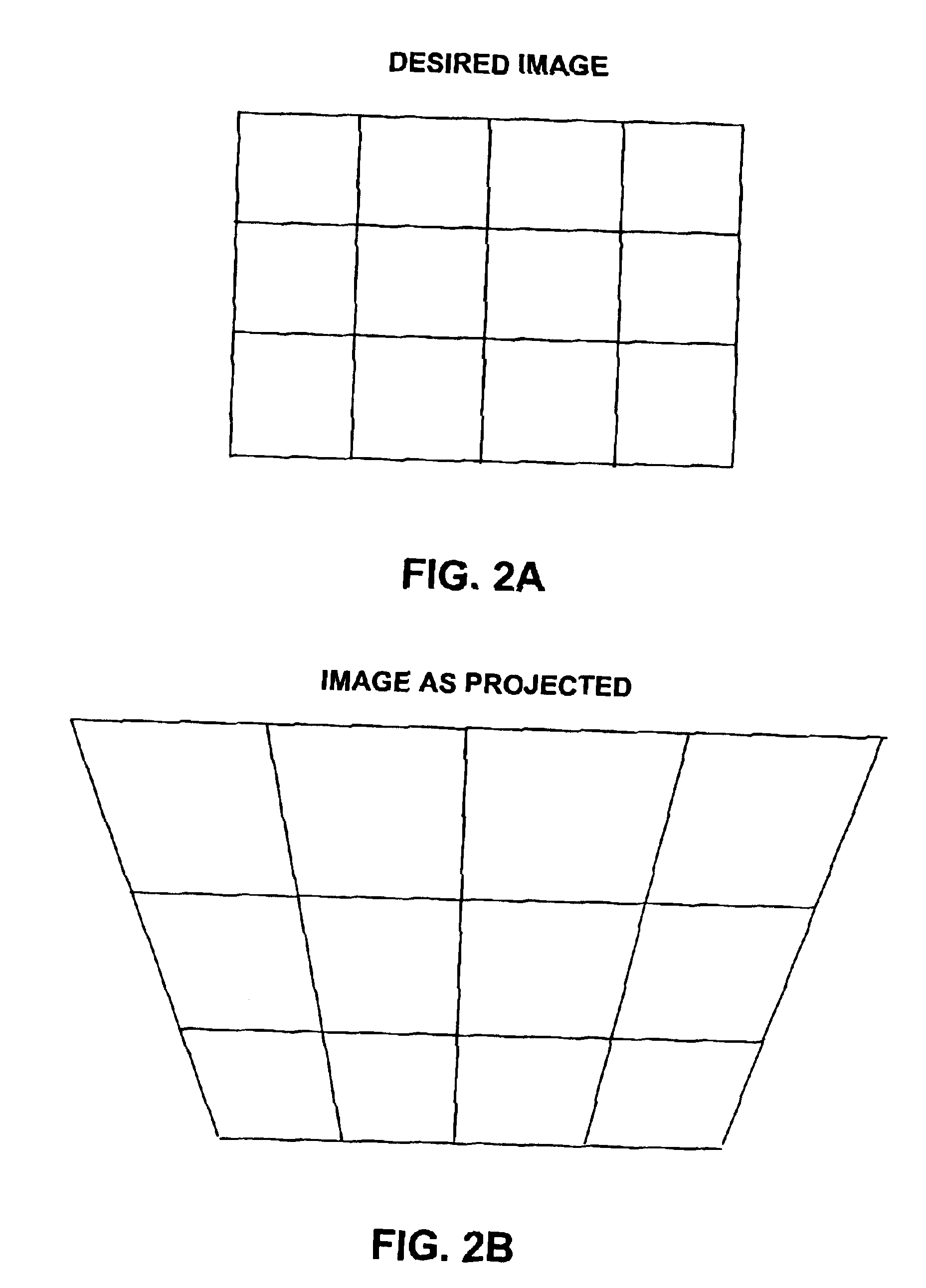
This off-axis vertical projection causes the top of the image, which is at a greater distance from the projection device than the bottom of the image, to subtend a larger portion of the projection surface than the bottom of the image in comparison to the input image as shown in FIGS. 2A and 2B resulting in vertical keystone distortion in the image.

Method used


Image

  • Automatic keystone correction system and method
  • Automatic keystone correction system and method
  • Automatic keystone correction system and method

Examples


Embodiment Construction

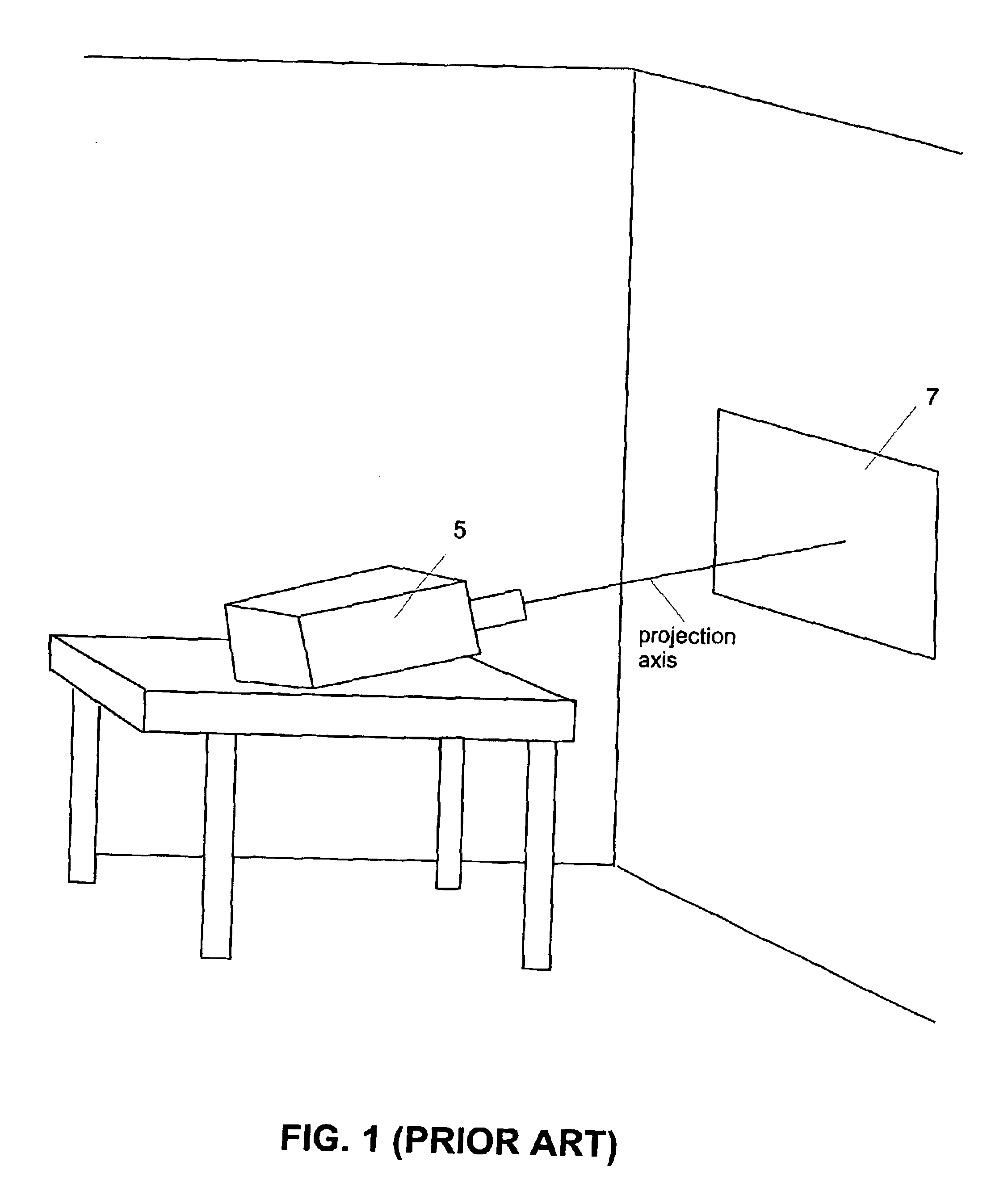
As previously discussed, conventional keystone correction projectors are concerned only with the effect of keystone distortion in a single, vertically oriented dimension. In the prior art tabletop configuration shown in FIG. 1, it is desirable to incline the axis of projection to raise the projected image above the plane of the table top. It is also highly desirable to be able to mount the projector 5 in such a fashion that the angle of the axis of projection in the horizontal dimension may be varied with respect to the normal vector of the projection surface. If the projector 5 is so mounted, the user is free to position the projector 5 almost anywhere in a given space. If the projector 5 is mounted such that it axis of projection is not perpendicular to the screen 7 in the horizontal direction but that its axis of projection is perpendicular to acceleration due to gravity in the vertical dimension (i.e. the axis of projection is in the plane of a flat tabletop), then the character...


PUM


Abstract

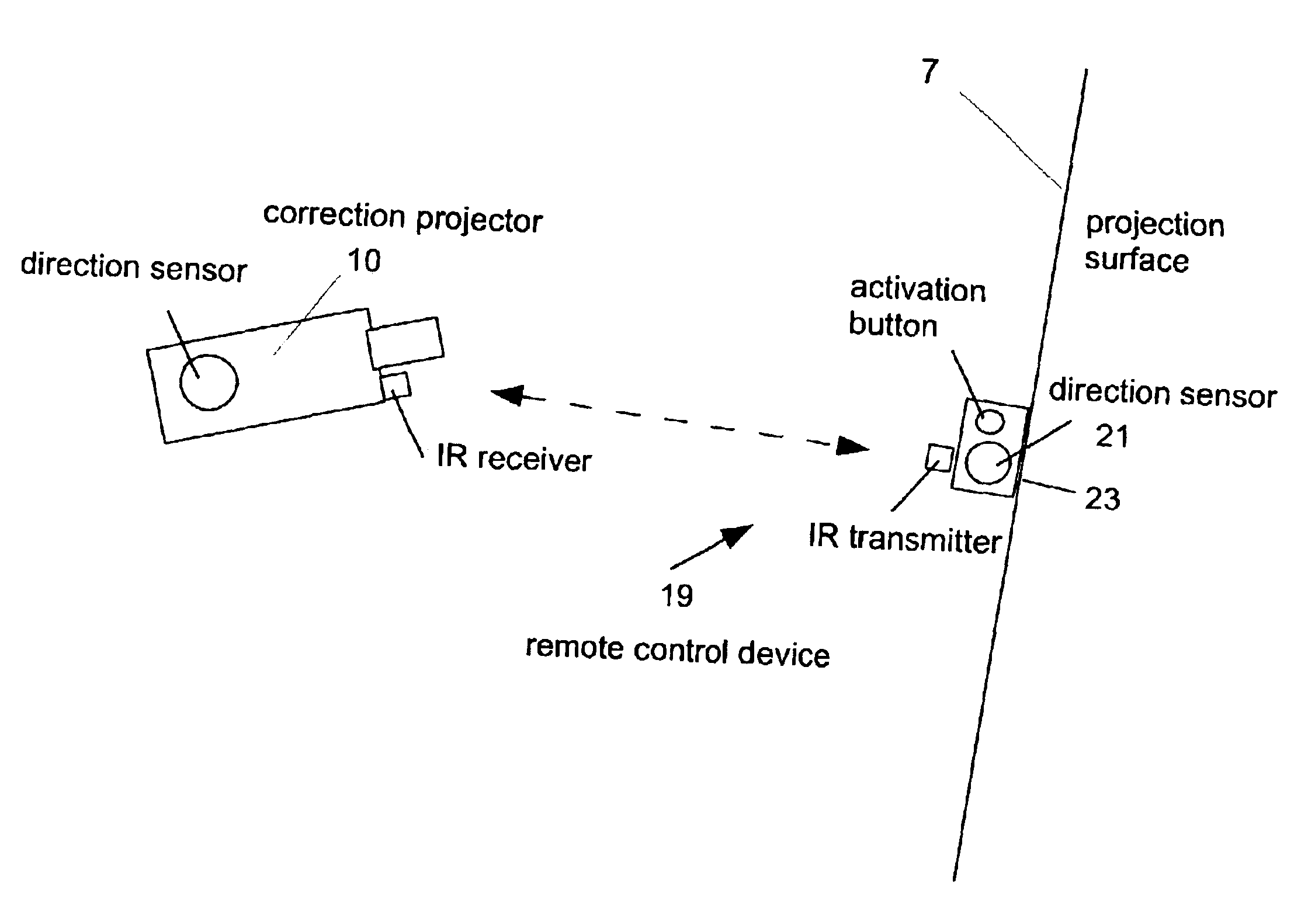
A projector assembly and method for automatically correcting keystone distortion includes an image correction engine, a light engine, a projection lens having a projection axis, a processor, a directional sensor and an inclination sensor. The sensors determine the absolute vertical and horizontal direction of the projection axis. The inclination sensor determines the vertical zero reference. The direction sensor is used to determine the horizontal zero reference. The processor calculates vertical and horizontal difference angles between the absolute directions and zero reference values in the vertical and horizontal directions. Using difference angles, the processor calculates the keystone distortion and instructs the image correction engine to apply geometric and brightness correction to the image data proportional and inverse to the keystone distortion and lens parameters (field of view, focal length, imperfections, etc) such that the image projected onto a viewing screen, is free from keystone distortion.

Description

FIELD OF THE INVENTIONThis invention relates to the field of data and video projection and more particularly to the removal of keystone distortion from a projection image.BACKGROUND OF THE INVENTIONComputer graphic and video projection devices have become commonplace and are in widespread use. Millions of business users are already using projection devices, and it is anticipated that additional millions of units will be used to provide entertainment viewing in the residential market. All so-called Front Projection Systems consist of a projection device that emits light, and a projection surface upon which this emitted light is reflected so that it may be viewed by the audience. Except in very unusual cases, the projection device, and the projection surface are two separate objects that may be oriented differently with respect to each other.FIG. 1 is a schematic diagram of a prior art projection system. As shown, a projection device 5 is often mounted on a tabletop, and the surface o...

Claims


Application Information

Patent Timeline
IPC IPC(8): G03B21/00G03B21/14G06T5/00H04N9/31H04N17/00
CPCG03B21/00G06T5/006H04N9/3197H04N9/3194H04N9/3185G03B21/005G06T5/80
Inventor WOOD, JOHN S.TABER, ROBERT L.RAMACHANDRAN, GOPAL
Owner GEO SEMICONDUCTOR INC
Learn More