Method for controlling operating cycle of impact device, and impact device

a technology of impact device and operating cycle, which is applied in the direction of portable percussive tools, drilling machines and methods, boring/drilling apparatus, etc., can solve the problems of reducing the efficiency of the impact device and leaking gaps are fairly wide, so as to simplify the structure of the impact device, simplify the effect of manufacturing and substantially constant impact speed

Inactive Publication Date: 2005-04-12
SANDVIK TAMROCK
View PDF17 Cites 21 Cited by
  • Summary
  • Abstract
  • Description
  • Claims
  • Application Information

AI Technical Summary

Benefits of technology

The invention is based on the idea of measuring the position of the percussion piston during an operating cycle using at least one sensor and transmitting the measurement data to a control unit controlling the percussion function of the impact device. On the basis of the measurement data and the control parameters supplied to the control unit, the control unit generates electric control signals for controlling at least one electrically driven control valve. The electrically driven control valve is configured to guide the pressure medium to act on the working pressure surfaces of the percussion piston so as to move the percussion piston in a desired manner during the operating cycle. An advantage of the invention is that the guiding of the pressure medium to the working pressure spaces of the percussion piston is not dependent on the precise mutual physical position of the percussion piston and the frame of the impact device. The impact device of the invention is thus more freely adjustable than prior art devices. The operation of the impact device can be changed, for different purposes and situations of use, by providing the control unit with new control parameters, without having to re-construct the physical structure of the impact device. For example, the invention allows the impact frequency and the impact speed of the device to be changed during drilling without requiring the impact pressure to be changed. Further, if the impact pressure is also measured, the impact speed can be kept substantially constant by regulating the operating cycle of the impact device. Moreover, the invention may simplify the structure of the impact device, because there are fewer control and pressure fluid ducts to be formed into the frame than before.
is that the guiding of the pressure medium to the working pressure spaces of the percussion piston is not dependent on the precise mutual physical position of the percussion piston and the frame of the impact device. The impact device of the invention is thus more freely adjustable than prior art devices. The operation of the impact device can be changed, for different purposes and situations of use, by providing the control unit with new control parameters, without having to re-construct the physical structure of the impact device. For example, the invention allows the impact frequency and the impact speed of the device to be changed during drilling without requiring the impact pressure to be changed. Further, if the impact pressure is also measured, the impact speed can be kept substantially constant by regulating the operating cycle of the impact device. Moreover, the invention may simplify the structure of the impact device, because there are fewer control and pressure fluid ducts to be formed into the frame than before.
An embodiment of the invention is based on the idea of guiding the working pressure flow through the electrically driven control valve to act on the working pressure surfaces of the percussion piston, and away from them. The operating cycle of the percussion piston is thus controlled directly by means of the control valve controlled by the control unit. Since the impact device does not comprise any mechanical control slides or ducts for guiding the control pressure to the slide, the structure of the described impact device is simpler and easier to manufacture than prior art devices.
An embodiment of the invention is based on the idea of using the electrically driven control valve to control the position of a mechanical slide. Depending on its position, the control slide opens and closes pressure fluid ducts, which allow pressure medium to flow into and out of the working pressure spaces of the percussion piston. In this solution the electrically driven control valve is used to provide an indirect control of the movements of the percussion piston because it is used as a pilot control valve to control the actual control element, i.e. the control slide. An advantage of this embodiment over direct control is that there are no great pressure medium flows to be guided through the electrically driven control valve, but only the control pressure flow needed for moving the control slide.

Problems solved by technology

A further drawback of known structures is that leakage gaps are fairly wide.
In addition, leakages naturally degrade the efficiency of the impact device.

Method used


Image

  • Method for controlling operating cycle of impact device, and impact device
  • Method for controlling operating cycle of impact device, and impact device
  • Method for controlling operating cycle of impact device, and impact device

Examples


Embodiment Construction

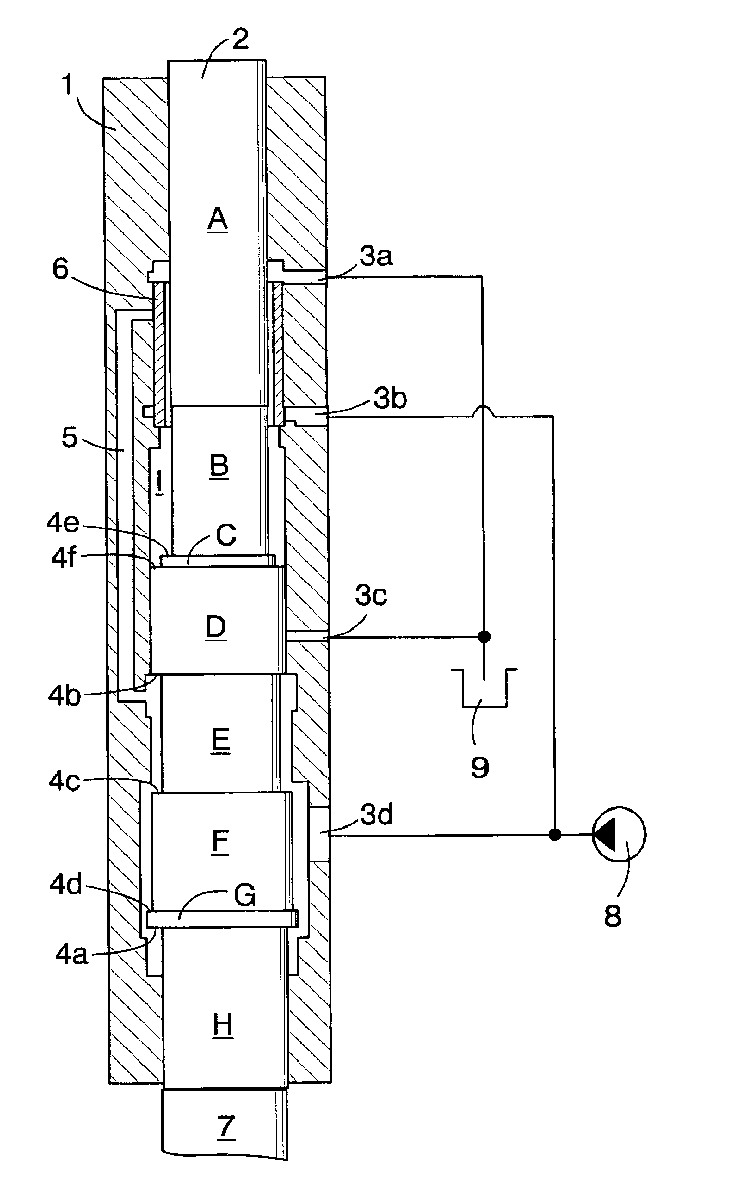
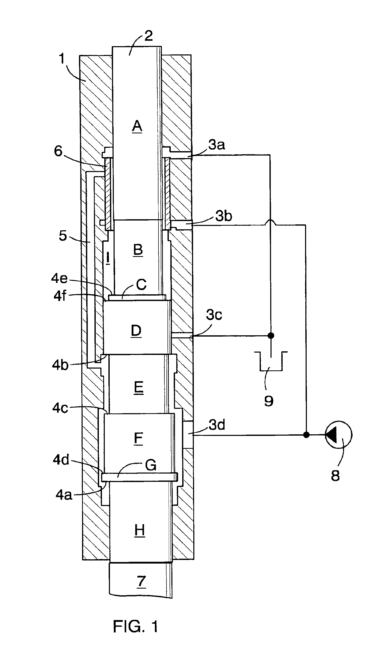
FIG. 1 shows the structure of a conventional impact device. The impact device comprises a frame 1 and a percussion piston 2 arranged to a cylinder space formed in the frame, the piston being moved in a longitudinal direction in relation to the frame 1. At the front end of the percussion piston, aligned with the piston, there is a tool 7. In a rock drilling apparatus, the tool closest to the impact device is the drill shank, which the percussion piston is arranged to strike. The impact force is delivered along drill rods, or similar tools attached to the drill shank, to the furthest element, i.e. the drill bit, which is thus driven into the rock by the impact. When the impact device is arranged to a percussion hammer, the percussion piston delivers blows to a chisel, which delivers the blows further to the object of the operation.

Seen from the rear end of the impact device, the percussion piston 2 comprises portions A—H of different diameters, whereby the percussion piston being thus...


PUM

PropertyMeasurementUnit
pressureaaaaaaaaaa
impact velocityaaaaaaaaaa
hydraulic pressureaaaaaaaaaa

Abstract

A method for controlling the operating cycle of an impact device, and an impact device. Percussion piston position is measured using a sensor (11) from which the measurement data is transmitted to a control unit (12) of the impact device, which in turn controls an electrically driven control valve (10).

Description

FIELD OF THE INVENTIONThe invention relates to a method for controlling the operating cycle of an impact device, the impact device comprising a frame, a percussion piston, working pressure surfaces formed on the percussion piston and acting both in the impact direction and in the return direction, working pressure ducts and discharge ducts for guiding pressure medium to act on the working pressure surfaces, and at least one control valve, the method comprisingvarying the pressure medium flows acting on the working pressure surfaces of the percussion piston, by means of the control valve, so as to produce a reciprocating impact and return motion according to the operating cycle of the percussion piston, and for delivering impacts on a tool arranged in the impact direction of the percussion piston.The invention further relates to an impact device comprising a frame, a percussion piston, working pressure surfaces formed on the percussion piston and acting in the impact direction and in...

Claims


Application Information

Patent Timeline
Patent Type & Authority Patents(United States)
IPC IPC(8): B25D9/18B25D9/26B25D9/00
CPCB25D9/18B25D9/26B25D2250/221
Inventor KOSKIMAKI, ANTTI
Owner SANDVIK TAMROCK
Why Eureka
Try Eureka