
Coupling for explosion-proof connection of two electric line ends

a technology of coupling and electric line, which is applied in the direction of coupling device connection, electrical apparatus, building components, etc., can solve the problems of unintentional disconnecting of electrical connections, unsuitable for mobile operations, and connecting hand-held devices, and achieves reliable and space-saving ways.

Inactive Publication Date: 2005-04-12
TIEFENBACH BERGBAUTECHN
View PDF9 Cites 58 Cited by
  • Summary
  • Abstract
  • Description
  • Claims
  • Application Information

AI Technical Summary

Benefits of technology

It is an object of the present invention to equip a coupling such that the two tube ends can be joined with each other by an easy rotational motion, without incurring the risk of disengagement, that despite the smooth operation, the alignment of the two tube ends adjusts automatically, and that the coupling can be constructed small, while complying with all safety requirements and operational ease. This and other objects of the present invention are provided in accordance with one aspect of the present invention by a coupling for providing an explosion-proof connection between electric line ends, with the coupling including tubes for being coupled to one another in an explosion-proof manner. The line ends are respectively accommodated in and permanently connected to the tubes, and each of the line ends includes a plug-in contact part with contact elements. The contact elements include a contact pin of one of the line ends and a contact socket of another of the line ends. The contact pin is for being plugged into the contact socket to provide a conductive connection between the contact elements. The contact elements are arranged so that the conductive connection exists while the tubes are coupled to one another in the explosion-proof manner. For each of the plug-in contact parts, the plug-in contact part includes a radial projection which functions as a stop that cooperates with a corresponding projection in the tube in which the plug-in contact part is accommodated. These projections axially secure the plug-in contact part in the respective tube to restrict movement of the plug-in contact part in a forward direction which extends from the plug-in contact part toward the other plug-in contact part while the tubes are coupled to one another in the explosion-proof manner. For each of the tubes, the tube's end into which the respective line ends enter the tube is closed by an insulating end cap, which sealingly surrounds the electric lines that enter the tube.
A circumferential bead arranged on the end cap can be used for axially securing the line in its coupling half in a reliable, but space-saving manner.

Problems solved by technology

A problem exists with a coupling of the type described above in that it is very large and heavy with all its necessary functional elements, so that it is unsuitable for a mobile operation, in particular for connecting hand-held devices.
Furthermore, the risk is incurred that the tube ends rotate relative to each other in the circumferential direction as a result of vibrations, or in any other fashion, so that the electrical connection disengages unintentionally.

Method used


Image

  • Coupling for explosion-proof connection of two electric line ends
  • Coupling for explosion-proof connection of two electric line ends
  • Coupling for explosion-proof connection of two electric line ends

Examples


Embodiment Construction

The following description applies to all embodiments and drawings, unless express reference is made to particularities and differences.

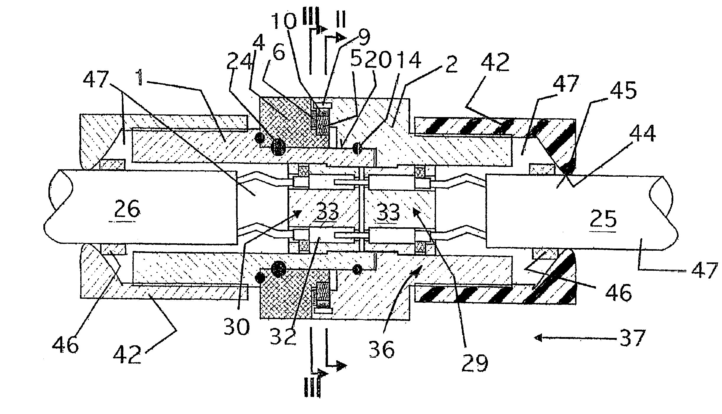
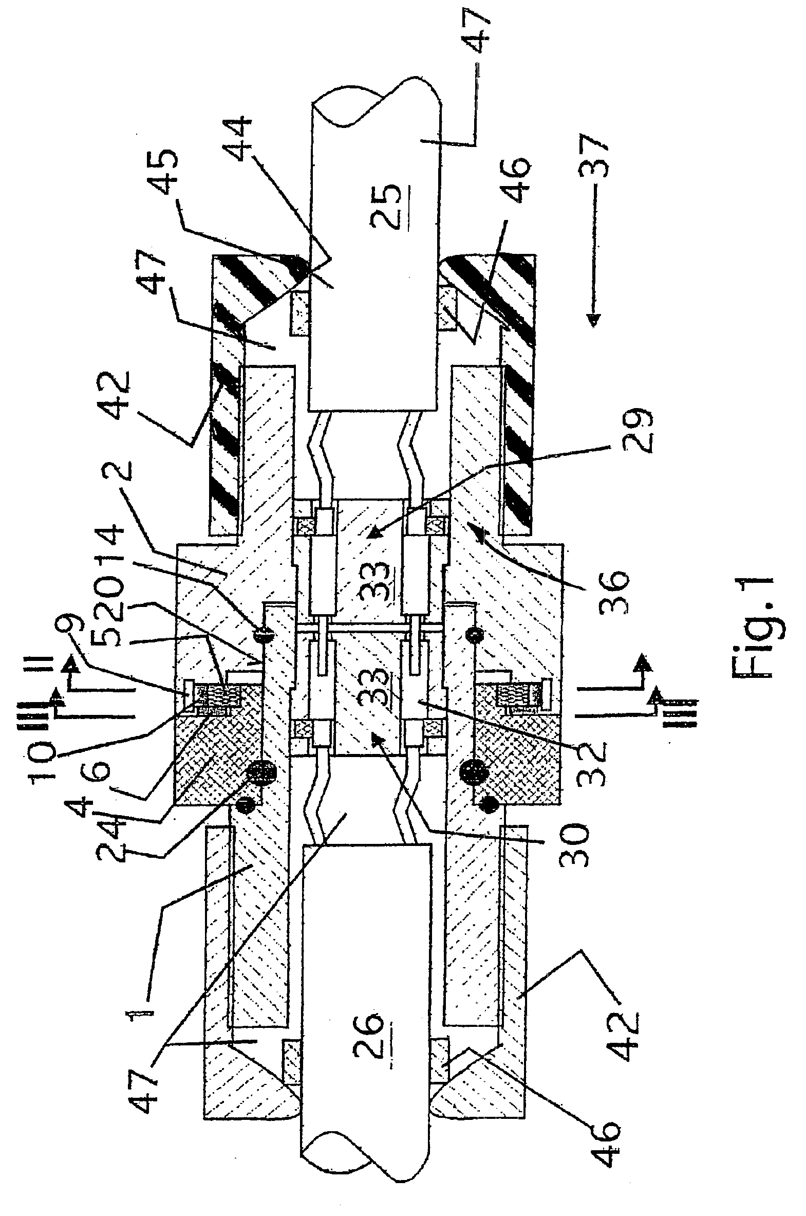
The illustrated tube ends are protective tubes for electric cabling. The tube ends accommodate plug-in connections, which create the electric contact of a user with a source of voltage by engaging the tube connections. Insofar, they may be in particular tube couplings, which ensure an explosion-proof, electric connection and are suitable for underground mining.

Description of the Coupling

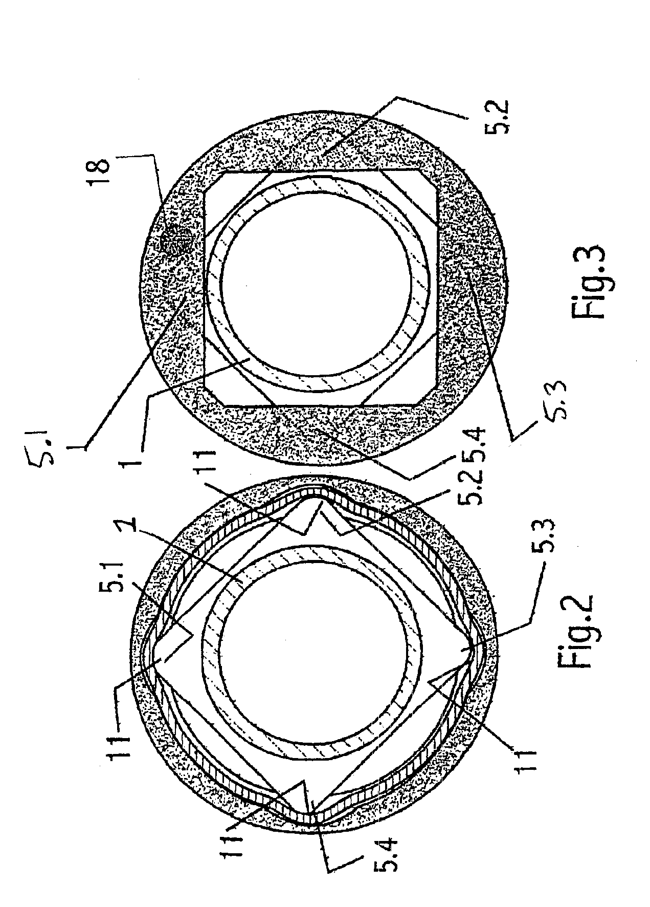
The coupling of FIGS. 1 and 10 consists of a cylindrical inner tube 1 and an outer tube 2. The outer tube is adapted to the inner tube with a narrow gap 20 therebetween. The cylindrical gap 20 is sealed by an O-ring 14. Due to its length and narrowness, however, the seal is also explosion-proof in line with regulations. Both tubes 1 and 2 are interconnected in a dustproof and fluid-tight manner by means of a bayonet joint 3, 4, which will be described further below.

En...


PUM


Abstract

For an explosion-proof connection of two electric line ends (25, 26), the contact elements (27, 28) are accommodated in two tubes (1, 2), which can be joined in an explosion-proof manner. Each of the plug-in contact parts is axially secured in its tube by a radial projection (41) in the direction toward the end facing the other tube. At its line end, each of the tubes is closed by an end cap (42), which sealingly surrounds with a narrow outlet (44) the electric lines, including an insulation (43). The tube, in which the plug-in contact part with the contact pins is axially secured, extends beyond the tip of the contact pins, and has there an enlarged diameter, with which it surrounds the other tube (inner tube 1,3) with a narrow cylindrical gap (sealing gap 20).

Description

BACKGROUND OF THE INVENTIONThe present invention relates to a coupling for an explosion-proof connection of two electric line ends with the coupling including tubes for being coupled to one another in an explosion-proof manner, the line ends being respectively accommodated in and permanently connected to the tubes, each of the line ends including a plug-in contact part with contact elements, the contact elements including a contact pin of one of the line ends and a contact socket of another of the line ends, the contact pin being pluggable into the contact socket to provide a conductive connection between the contact elements, and the contact elements being positioned so that the conductive connection exists while the tubes are coupled to one another in the explosion-proof manner.Couplings of the type described above are generally known. A problem exists with a coupling of the type described above in that it is very large and heavy with all its necessary functional elements, so that...

Claims


Application Information

Patent Timeline
IPC IPC(8): H01R13/527H01R13/625
CPCH01R13/527H01R13/625
Inventor KUSSEL, WILLIREINER, FRANK
Owner TIEFENBACH BERGBAUTECHN
Learn More